


11
£
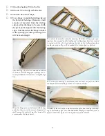
25 Note along the top of the trailing edge
the small indentations to locate the flap
hinges. When you plane the trailing
edge to contour with the ribs in prepa-
ration for sheeting you will remove the
part that would be visible after sheet-
ing. To mark these locations for visibil
-
ity after sheeting make a shallow saw
cut so that the kerf will be visible after
sheeting, then plane the trailing edge to
contour with the ribs.
£
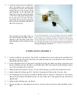
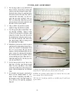
26 Install and glue W2-B Top to the out-
board end of WBP.
Here WBP has been installed as well as WPBF and W2-B at the left end of
WBP. WBP (wing bolt plate) is filled flush to the ribs by WBPF and will sup
-
port the wing sheeting when the wing bolts are installed.
£
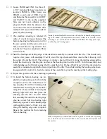
27
Glue two HPB (hinge point blocks) at
each hinge hole in TE-C, the aileron
bay.
£
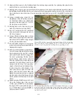
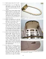
31
Locate one FSM (flap servo mount) and
one ASM (aileron servo mount) and a
pair of FSMR (flap servo mount rails)
and a pair of ASMR (aileron servo
mount rails). The rails will be glued to
the ribs and then the servo mounts will
be attached to them with #1 x 3/16” flat
head wood screws. Determine the cor-
rect orientation of ASM and FSM and
countersink the screw holes for the flat
head screws. They will sit flush to the
surface when finished. The easiest way
to assure that everything will line up
when finished is to temporarily attach
The flap and aileron mounts and their screw rails are temporarily assembled
and then the rails are glued into there respective ribs. The servo mounts
are then removed. This method assures perfect alignment of the components
The flat head wood screws are countersunk to fit flush to the surface of the
servo mounts. Note the materiel sticking out beyond the edges of the servo
mount. This will provide a small shelf to support the wing sheeting.
£
39 Install and glue WBPF.
£
30 Install and glue the bottom section of
W2-B.
£
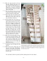
28 Carefully remove the pins holding the
assembly to the building board and turn
the assembly over. Do not remove the
stand off’s and pinning tabs at this time.
Were not quite through with them. Pre-
pare the bottom of the sheer web by
removing any nubs and then install the
bottom spar flange as you did the top
one. The exact position is correct when
the spar butts against W6 and lays in the
notches on the top of the ribs. The top
spar flange should be flat on the bench.
To provide more support for the aileron hinge points, these hinge blocks
are added to the trailing edge of the aileron bay.


