


4
RUDDER ASSEMBLY
The rudder is composed of three sections that are glued together. The core sheet or center lamination con-
tains openings for the hinges as well as the rudder torque rod. You will use the pin registration method to
assemble these three components.
£
1 Locate and prepare one RC and two
RUD parts. Place one RUD on the reg-
ister pins. I do not recommend CA for
this assembly; instead use an adhesive
that you can spread a thin layer onto the
surface of RC. This can be Aliphatic
Resin or spray on contact cement. You
will want a thin but firmly glued joint
between the three sections when you
go to shape the final part. Apply a thin
layer of adhesive to the correct side of
RC and then slide it down the pins into
contact with RUD.
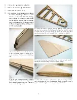
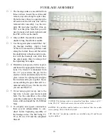
One RUD part has been placed on the register pins and the core (RC) has
been coated with spray adhesive and is about to be pushed down the register
pins and into contact with RUD. Note that the rudder core sheet contains the
hinge pin openings precisely aligned with those in the vertical fin. Also on
the right is a slot for the rudder torque rod. Note the half moon key at the left
end that will receive the tip assembly.
£
2 Apply a thin layer of adhesive to the re-
maining RUD and slide it down the pins
and into contact with the assembly. Re-
move from the pins and put under pres-
sure until cured.
£
3 The leading edge of the rudder assem-
bly will need to be double beveled to
accommodate the swing of the rudder.
I prefer to do this on a band saw set to
35° angle. Note that this will only work
before shaping the airfoil. Using a razor
plane will work as well.
£
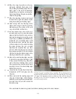
4 Three 1-1/2” pieces of music wire are
used in the hinge pockets to hold the
rudder and vertical fin in perfect align
-
ment. Then the leading edge of the rud-
der is marked for shaping.
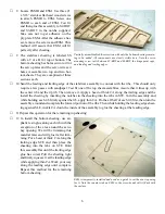
On the left is the vertical fin assembly with steel pins temporarily replacing
the hinge pins and on the right is the rudder assembly. The double bevel
on the rudder was cut using a band saw set at 35°. The rudder has been
removed from the steel pins after marking the leading edge with the fin trail
-
ing edge. The rudder assembly can now be tapered to match the fin. The
rudder torque rod is only temporarily installed and will be removed before
finishing.
£
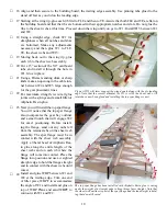
5
First plane the rudder down to the thick
-
ness indicated by these lines and then
introduce into it the airfoil shape.
£
6
Assemble the two RT pieces and then glue onto the tip of the rudder. Place the assembly back onto the fin
using the pins and mark the counter balance (the material that sticks forward of the hinge line) along the
fin for a trimming guide. The counter balance should be the same width as the fin. Then trim and sand to
contour with the rudder.


