


7
c
2
c
1
c
38
c
37
c
36
c
35
c
34
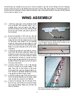
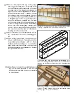
Sand the leading edge smooth. Install and
glue the leading edge (LE). Use pins to sta-
bilize it and tape to pull it snugly against
FLE.
Plane and sand the leading edge shape to
contour. Use the leading edge template to
guide your work
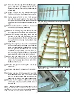
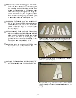
Locate three Wing Tip (WT) parts and use
the registration pins to laminate the three
together to make the wing tip block. Glue
this assembly to W11 and when cured,
plane and sand to shape.
In the circles above are two gussets made from 1/4” triangle
stock, use on both sides. The arrow in th lower part is indica
-
tion the glue fillet between the cap strip and the rib.
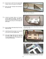
Sand the trailing edge in the aileron bay flat
and install and glue the Aileron Bay Trailing
Edge (ABTE). Sand ABTE to contour with
the trailing edge and wing tip. Use a knife
blade to open up the slot for the hinges and
test fit the hinges for easy installation, they
should fit slightly snug.
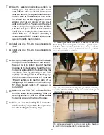
Use some scrap balsa to fill in at the front
and back the servo plate (SP) opening. Use
the Servo Plate as a guide.
This concludes the assembly of one wing panel. Place the remaining wing panel plans on the building
board and repeat all the above Wing Assembly Steps. Joining the wing halves will be done later after
we assemble the belly pan.
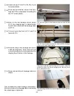
Assembling the Ailerons
Each aileron is laminated up from two (AIL)
parts using the registration pins to assem-
ble them. After laminating two AIL,s sand
the leading edge and both ends smooth.
NOTE: Although the ailerons will not be permanently attached until after the model is covered, cutting
the hinge slots and temporarily fitting the assembly together will make the final assembly mush easier.
Place the aileron next to the trailing edge
and mark the location of the hinges on the
aileron, then cut slots to accept the hinges.


