


6
c
33
c
32
c
31
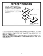
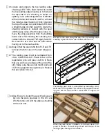
Assemble the center section sheeting from
one TCS and one BCS section and glue it
to ribs W1, W2 and W3 as well as the spar
and TE.
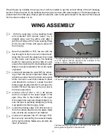
Installing the bottom leading edge sheet-
ing. The curve on the bottom leading edge
should not require wetting the balsa, install
it dry. Apply a bead of alphabetic resin (El-
mer’s or Titebond) to all ribs and the FLE.
Use a bead of medium CA on the top of the
spar and place the leading edge sheeting in
place and into contact with the spar. Hold it
in that position until the CA has cured. Place
the assembly on the bench with the sheeting
on the bottom and run a sharp blade along
the edge of FLE and trim the sheeting flush
with FLE. Then use strips of masking tape
around the leading edge to pull the sheeting
into contour and into contact with the ribs
and FLE. Set aside to cure.
c
30
c
29
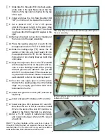
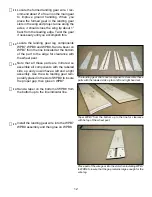
Install and glue the Wing Servo Rails (WSR)
into the notches provided in W7 and W8.
Note that the screw holes should be to the
inside or towards each other. Use 1/4” piec-
es of 1/4” triangle stock to gusset these to
the ribs.
Install the servo rails and use some 1/4” length pieces of 1/4”
triangle stock as gussets between the ribs and the rails.
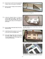
Sand the trailing edge to contour with the
ribs between W7 and W10 in preparation
for installing the trailing edge sheeting. In-
stall and glue the trailing edge sheeting to
ribs W1 through W7, the trailing edge and
the top trailing edge sheeting. Use clamps,
clothes pins or weights to maintain contact
with the ribs, trailing edge and top sheeting
until the glue cures.
When installing the bottom trailing edge, use plenty of clamps
along the trailing edge. A slight taper on both sheets will yield
a nice crisp trailing edge.
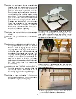
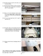
The cap strips are laser cut and should re-
quire little or no trimming to install. Note that
cap strips 7 and 8 on the bottom are notched
for the servo opening, after installing 7 and
8 on the bottom, run a bead of glue along
the interface of the rib and the cap strip on
the outside of the servo bay for support. In-
stall all cap strips, top and bottom, the num-
bers on the cap strips corresponds to the rib
they will attach to.
The cap strips on the bottom of ribs 7 and 8 are shaped to
accommodate the servo opening. The material indicated by
the arrows is scrap fill. You can use the servo mount for po
-
sitioning of the fill.


