Top Notch Products MINI SUPREME Manual Download Page 12

10

3

2

1

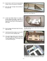
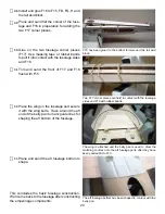
Locate the four wheel pant halves. Note 

that two of them have dimples in them for 

the attachment system. Drill the four small-

er dimples out with a 1/16” bit. Drill out the 

larger dimple with a 1/8” drill bit.
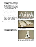
Trim the parts down to about 1/4” from the 

edge of the part in preparation for trim-

ming out with the trim tool. You will need a 

smooth flat surface for the next operation.

While holding the part flat on a smooth sur

-

face make many very shallow cuts around 

the periphery of the part. Do not attempt to 

cut through but instead just try to score it. 

It may take ten or fifteen very light passes, 

if you put too much pressure it can deflect 

the blade. Some parts of the plastic are 

thinner than others and if you do happen 

to break through, no problem just back off 

on the pressure and continue. After you are 

satisfied with the scoring, fold the edge of 

the rim inward and it should break along 

the score. Continue all the way around the 

part. If there are any irregularities, a couple 

swipes on a flat piece of sand paper should 

clean up the edge.

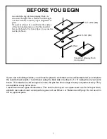
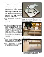
Landing Gear Assembly

The landing gear and wheel pants are assembled as a unit and then installed in the wing. To assemble 

the wheel pants they must first be trimmed to shape. This is easily accomplished using the plastic trim

-

ming tool but first we need to assemble the tool. Locate both parts of the trim tool. Note the tracing of 

the X-Acto blade on one part. Use thin CA to glue the X-Acto blade to the part. Then glue the second 

Trim Tool part to the first encapsulating the blade.

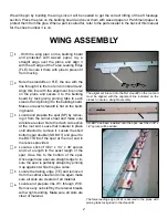
RIGHT: The trimming tool components, a new blade must 

be used when assembling the tool. The tool is used to only 

score the plastic. The scrap can then be removed by flexing  

at the score. This will give you a clean straight edge to work 

with.

Scoring the plastic with the trimming tool will give you a clean 

straight edge to work with.

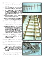
With a good score, the plastic will snap along the score line 

leaving a straight edge.

Summary of Contents for MINI SUPREME

Page 1: ...TOP NOTCH PRODUCTS MINI SUPREME Top Notch Products Company PO Box 1051 Goodlettsville TN 37072 Phone 615 866 4327...

Page 2: ......

Page 3: ...in the block If your new to building models you will need a place to work that can be undisturbed until you complete the build for best results I recommend using the back side of a drop in 2 x 4 ceil...

Page 4: ...ndoff on the root end must be aligned with the alignment line indicated on the planes to insure a straight assembly Alignment Line Locate and prepare the spar SP by remov ing it from the carrier sheet...

Page 5: ...line in the TE standoff with the alignment line on the plans and se cure it to the building board with a pinning tab tack glued to the standoff Like you did with FLE Continue down TE and secure ev ery...

Page 6: ...tboard side of W3 Install and glue W4 A to the outboard side of W4 As cut the trailing edge should be flush with the top of the ribs between the root and W7 However it will be slightly proud of the tr...

Page 7: ...he spar the top leading edge sheeting is glued from the open bottom with thin CA Snap off all the stand offs from FLE and TE but save them for use on the next wing pan el The landing gear block is lam...

Page 8: ...tall the servo rails and use some 1 4 length pieces of 1 4 triangle stock as gussets between the ribs and the rails Sand the trailing edge to contour with the ribs between W7 and W10 in preparation fo...

Page 9: ...e a knife blade to open up the slot for the hinges and test fit the hinges for easy installation they should fit slightly snug Use some scrap balsa to fill in at the front and back the servo plate SP...

Page 10: ...Note that BP 11 terminates in an angle at one end this is the AFT end Starting at the front or opposite end install and glue BP 1 to BP 11 Install BP 3 BP 5 BP 7 and BP 9 from the front to the back I...

Page 11: ...WING HALVES Cut a 1 2 length of 1 8 dowel and round over one end Install it in the hole provided in W1 just ahead of TE let it protrude about 1 8 Do this in one wing half only this will engage the hol...

Page 12: ...ard and it should break along the score Continue all the way around the part If there are any irregularities a couple swipes on a flat piece of sand paper should clean up the edge Landing Gear Assembl...

Page 13: ...e entire periphery on the inside of the part and then install the joiner Use clothes pins or clamps to insure good contact with the joiner Remove any glue that squeezes out so as not to inter fear wit...

Page 14: ...g gear strut cover components Assemble these parts with the labeled side up for a left and right hand set Note that all these parts are mirrored so assemble all components with the labeled side up and...

Page 15: ...pport button Install and glue WPB 8 to WPB 9 Glue WPB8 to WPB9 Remove the four screws and install the wheel then reinstall the four screws Final installation of the mains gear will be done after cover...

Page 16: ...degrees to each other Former A firewall and former B assembled with he battery deck BD Use the square to keep all these components square to each other Glue the battery deck assembly to the fuse lage...

Page 17: ...a to 11 long and install and glue them into the notches provided in formers E1 F G and H When the glue has set remove the TEMP GUIDE Step 13 Step 14 Locate the Turtle Deck Sheeting TDS Install and glu...

Page 18: ...B1 and C1 Lightly sand the outer edges of HA B to remove any nubs and smooth the sides When the hatch is completed HA B will slide down between the fuselage sides Use the 1 8 dowel pins and assemble...

Page 19: ...hatch pull on the front of the hatch centered and about 5 16 back from the front Mark the hatch sheeting for the opening Cut the opening and test fit the hatch pull Place a 1 8 x 1 4 magnet into the h...

Page 20: ...rectly in the wing saddle W13 should butt firmly against former B Sand the sheeting flush with former B and the fuselage sides Install the 8 32 Nylon bolts through the bolt wells and then through the...

Page 21: ...the wells Remove the wing from the fuselage and sand the trailing edge flat and to contour with BP10 The marks transfered from the paper taped to the fuselage are carefully opened up to the diameter...

Page 22: ...fuselage sides and F16 with rubber bands Trim and sand the front of F17 and F16 flush with F15 Place the wing on the fuselage and secure it with the wing bolts Trace around the aft end of the belly pa...

Page 23: ...will engage the fuselage ELEVATOR ASSEMBLY Place the elevator halves over the plans Use a straight edge secured them to the building board to insure they are straight Pin the elevator halves in positi...

Page 24: ...ing and in stalling onto the fuselage c 5 c 4 c 3 c 2 c 1 c 5 c 4 c 3 c 1 c 2 VERTICAL FIN ASSEMBLY Place the vertical Fin plan on the bench and cover with waxed paper Position V3 over the plans and s...

Page 25: ...clamp them Place the axle in both parts to insure align ment of the axle holes and then glue the two halves together With the axle temporarily installed to insure alignment the as sembly is clamped a...

Page 26: ...he long way Place it up against the corner of the verti cal fin and the stabilizer and hold it in place with clamps Use a straight edge along the turtle deck to extend the angle of the deck and mark t...

Page 27: ...oard and let it cure Use some scrap wood pressed against the sides to make sure the cowl is in contact with the cowl ring The sides should be flat A series of 1 8 holes is drilled along the perimeter...

Page 28: ...7 x 36 piece of music wire Round over and make smooth both ends of the 047 x 36 wire Use a pliers to bend the ends into the shapes indicated on the plans Measure in three inches from the last bend and...

Page 29: ...he wing onto the fuselage and se cure it with the wing bolts Glue the two fillet supports to the fuselage at the trailing edge of the wing The fillet supports butt against the wing but glue to the fus...

Page 30: ...ces All support of the servo should be provided through the rubber vibration absorbing grommets supplied with the servo Place the servo on the surface it will be mounted to with a 1 32 spacer undernea...

Page 31: ...In this case they have been raised 1 8 with a piece of 1 8 x 1 4 basswood to allow a recessed cockpit floor Builders preference The screw pattern supplied is for the HS255MG servos If oth er servos a...

Page 32: ...22 BALSA 1 16 X 4 X 36 A 1 11 AC PLY 1 8 X 4 X 16 A1 1 10 LPLY 1 8 X 6 X 29 ABTE 2 23 BALSA 1 16 X 4 X 36 AFB 1 10 LPLY 1 8 X 6 X 29 AIL 4 1 BALSA 1 4 X 4 X 36 B 1 11 AC PLY 1 8 X 4 X 16 B1 1 10 LPLY...

Page 33: ...36 FCS 2 28 BALSA 3 32 X 3 X 36 FLE 2 7 BALSA 1 8 X 4 X 36 FS 1 8 BALSA 1 8 X 4 X 36 FS 1 9 BALSA 1 8 X 4 X 36 FSD 2 15 AC PLY 1 64 X 6 X 15 FST 1 10 LPLY 1 8 X 6 X 29 G 1 10 LPLY 1 8 X 6 X 29 GB 1 10...

Page 34: ...36 R6 1 4 BALSA 1 4 X 4 X 36 R7 1 4 BALSA 1 4 X 4 X 36 S1 1 4 BALSA 1 4 X 4 X 36 S2 1 4 BALSA 1 4 X 4 X 36 S3 2 4 BALSA 1 4 X 4 X 36 S4 1 4 BALSA 1 4 X 4 X 36 S4 1 4 BALSA 1 4 X 4 X 36 S6 2 4 BALSA 1...

Page 35: ...B 4 11 AC PLY 1 8 X 4 X 16 W2 C 2 13 AC PLY 1 32 X 3 X 8 W3 2 20 BALSA 1 16 X 4 X 36 W3 A 2 14 AC PLY 1 16 X 6 X 19 W4 2 20 BALSA 1 16 X 4 X 36 W4 A 2 14 AC PLY 1 16 X 6 X 19 W5 2 20 BALSA 1 16 X 4 X...

Page 36: ...Servo Covers 8 Plated 1 x 3 8 SM Screw Wheel pant attach 3 Balsa 3 16 x 3 16 x 36 Stick Wood AFT Fuselage Sides 4 Spruce 3 32 x 1 4 x 36 Stick Wood Wing Spar 2 Wheel 2 Wheel Mains 1 Wheel 1 Wheel Tai...

Page 37: ...35 BELLY PAN HATCH PULL PUSHROD EXIT GUIDES BELLY PAN BOLT WELLS WHEEL PANT SCREW PLATES TAIL WHEEL SHROUD RIGHT INBOARD LEFT INBOARD LEFT OUTBOARD RIGHT OUTBOARD Plastic component identification...

Page 38: ...Top Notch Products Company PO Box 1051 Goodlettsville TN 37072 Phone 615 866 4327...

Reviews: