


5.10 Measurement auxiliary setting
5-25
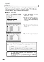
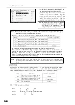
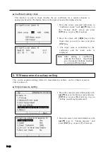
○ Simple measure
The section “5.3: Coefficient, indication digits, and unit” explains how to set parameters
for measurement data for each measurement channel. On the other hand, the function
to set certain fixed parameters at one time is also available. That function is called
“Simple measure”, and allows automatic setting of parameters shown in the list below,
corresponding to the set sensor mode.
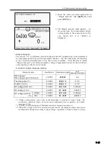
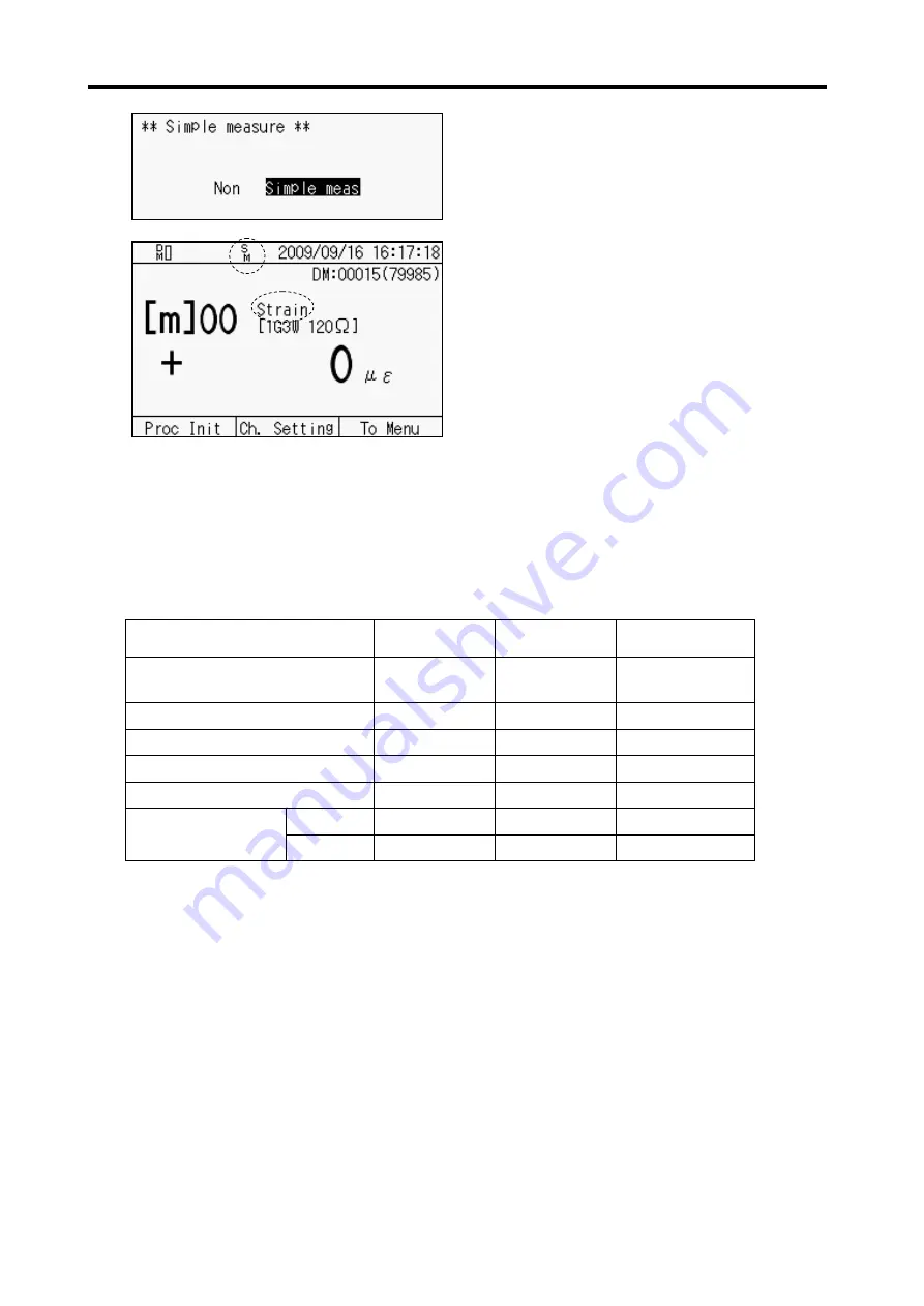
Content of simple measure setting
Sensor mode
Coefficient
Indication digits
Unit
(display example)
Strain gauge
Strain gauge type transducer
+1.0000
######
1
με
Thermocouple (*1)
+1.0000
#####
.
#
0.1°C
Pt-RTD (*1)(*2)
+1.0000
#####
.
#
0.1°C
DC voltage (300 mV)
+1.0000
###
.
###
0.001mV
DC voltage (30 V)
+1.0000
##
.
####
0.0001V
DC voltage (AUTO)
(*3)
~
300mV
+1.0000
###
.
###
0.001mV
~
30V
+1.0000
##
.
####
0.0001V
*1: When a temperature sensor such as thermocouple is selected in Sensor mode , the
coefficient, indication digits, and unit are automatically fixed regardless of Simple
measure setting.
*2: Pt-RTD is an abbreviation of Platinum resista nce temperature detector.
*3: When DC voltage (AUTO) is selected in Sensor mode, the indication digits and unit are
automatically changed according to input voltage, regardless of Simple measure setting.
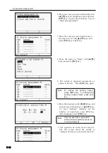
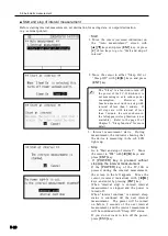
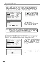
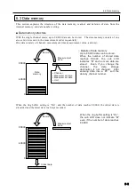
3. Move the cursor (reversed indication) to
“Simple measure” with
[▲][▼]
keys and
press [
ENT]
key.
4. The Simple measure mark appears. At
the same time, the measurement object
corresponding to the sensor mode (in the
case shown left, it is “Strain”) is
displayed.
Summary of Contents for TC-32K
Page 1: ...O p e r a t i o n M a n u a l TC 32K HANDHELD DATA LOGGER...
Page 8: ...Chapter 12 Error Message 12 1 Explanations and countermeasures for error messages 12 2...
Page 9: ...Chapter 1 Overview 1 1 Overview 1 2 1 2 Features 1 2 1 3 Details about each part 1 3...
Page 22: ...2 5 Operation outline 2 10 memo...
Page 23: ...Chapter 3 Sensor Connection 3 1 Sensor connection 3 2...
Page 65: ...5 10 Measurement auxiliary setting 5 28 memo...
Page 78: ...6 5 Recording in data memory and CF card 6 13 memo...
Page 86: ...7 7 Remote measurement 7 8 memo...
Page 98: ...8 7 Factory setting 8 12 memo...
Page 127: ...11 4 Outside drawing 11 8 11 4 Outside drawing Unit mm...
Page 128: ...Chapter 12 Error Message 12 1 Explanations and countermeasures for error messages 12 2...