


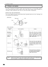


3.1 Sensor connection
3-4
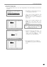
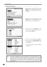
Measurement
object
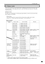
Wire connection diagram
Sensor mode
Transducer
with NDIS
connector plug
4GAGE
4G
C350Ω
4G 0-2V
Transducer
without
connector
4GAGE
4G
C350Ω
4G 0-2V
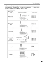
Thermocouple
temperature
measurement
Thermocouple
T, K, J, B
S, R, E, N
Direct current
voltage
measurement
DC voltage
300mV
DC voltage 30V
DC AUTO
(up to 30V)
Pt-RTD
(Platinum
resistance
temperature
detector)
Pt100 3W
Red
Green
Black
White
+
̶
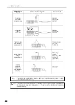
For most of our transducers
You cannot use a calibrator or an equivalent, which has the input connector F and G
connected for remote sensing.
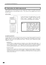
Note
Lead wire color of transducer may be different from the above diagram depending on
the transducer type and manufacturer. Please read the transducer
’s operation
manual carefully.
Warning
Summary of Contents for TC-32K
Page 1: ...O p e r a t i o n M a n u a l TC 32K HANDHELD DATA LOGGER...
Page 8: ...Chapter 12 Error Message 12 1 Explanations and countermeasures for error messages 12 2...
Page 9: ...Chapter 1 Overview 1 1 Overview 1 2 1 2 Features 1 2 1 3 Details about each part 1 3...
Page 22: ...2 5 Operation outline 2 10 memo...
Page 23: ...Chapter 3 Sensor Connection 3 1 Sensor connection 3 2...
Page 65: ...5 10 Measurement auxiliary setting 5 28 memo...
Page 78: ...6 5 Recording in data memory and CF card 6 13 memo...
Page 86: ...7 7 Remote measurement 7 8 memo...
Page 98: ...8 7 Factory setting 8 12 memo...
Page 127: ...11 4 Outside drawing 11 8 11 4 Outside drawing Unit mm...
Page 128: ...Chapter 12 Error Message 12 1 Explanations and countermeasures for error messages 12 2...