


3.1 Sensor connection
3-3
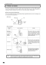
■
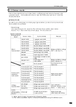
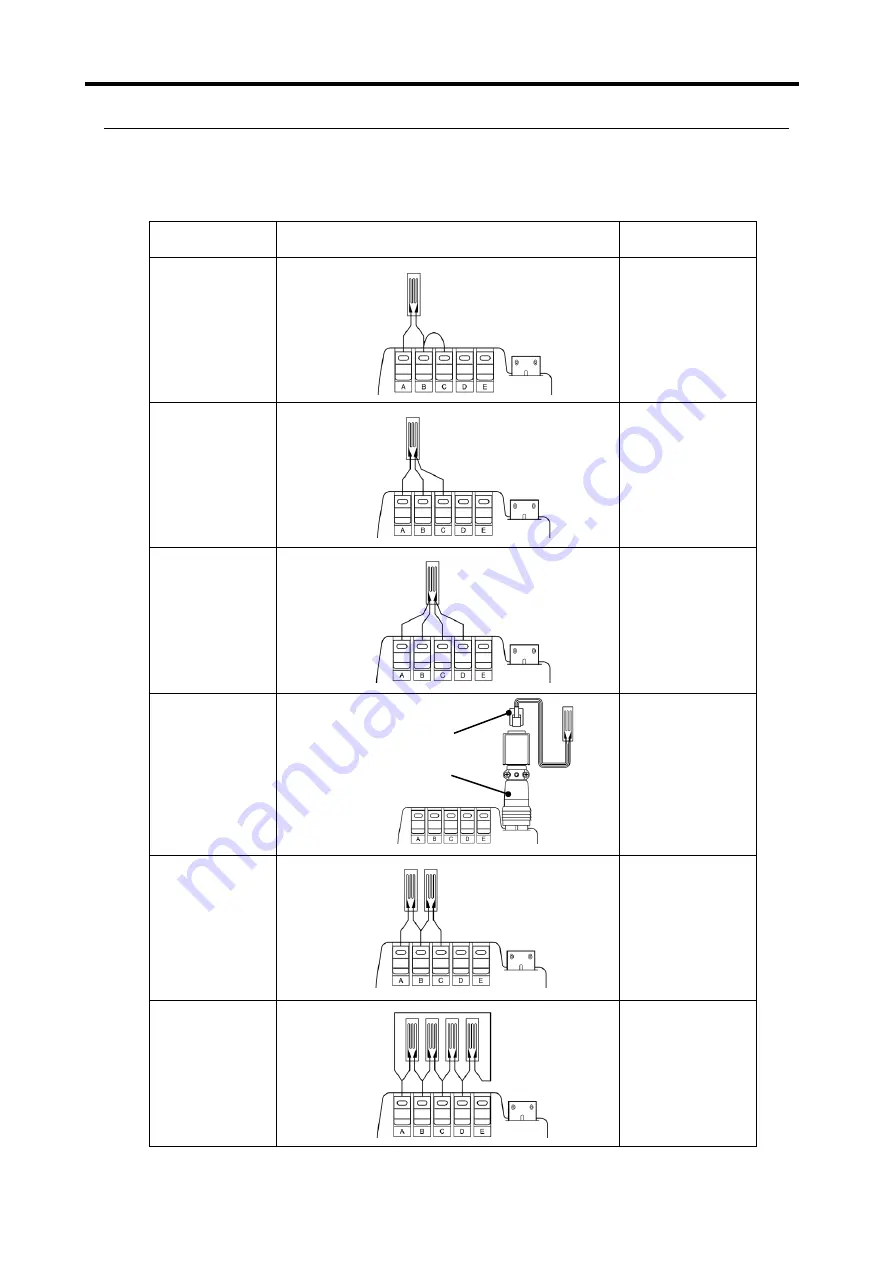
Wire connection by sensor type
Wire connection procedure varies according to type of the sensor to be measured. The table below shows
the connection procedure and the proper sensor mode for each sensor.
○
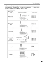
Wire connection table
Measurement
object
Wire connection diagram
Sensor mode
Quarter bridge
2-wire
1G3W
120Ω
1G3W
240Ω
1G3W
350Ω
Quarter bridge
3-wire
1G3W
120Ω
1G3W
240Ω
1G3W
350Ω
1-gauge 4-wire
1G4W
120Ω
1G4W
240Ω
1G4W
350Ω
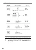
1-gauge 4-wire
conversion
adapter
(optional item)
1G4W 1
20Ω
1G4W
240Ω
1G4W
350Ω
Half bridge
2GAGE
Full bridge
4GAGE
4G
C350Ω
4G 0-2V
Modular connector
1-gauage 4-wire
conversion adapter
Short between B and C
with lead wire
Summary of Contents for TC-32K
Page 1: ...O p e r a t i o n M a n u a l TC 32K HANDHELD DATA LOGGER...
Page 8: ...Chapter 12 Error Message 12 1 Explanations and countermeasures for error messages 12 2...
Page 9: ...Chapter 1 Overview 1 1 Overview 1 2 1 2 Features 1 2 1 3 Details about each part 1 3...
Page 22: ...2 5 Operation outline 2 10 memo...
Page 23: ...Chapter 3 Sensor Connection 3 1 Sensor connection 3 2...
Page 65: ...5 10 Measurement auxiliary setting 5 28 memo...
Page 78: ...6 5 Recording in data memory and CF card 6 13 memo...
Page 86: ...7 7 Remote measurement 7 8 memo...
Page 98: ...8 7 Factory setting 8 12 memo...
Page 127: ...11 4 Outside drawing 11 8 11 4 Outside drawing Unit mm...
Page 128: ...Chapter 12 Error Message 12 1 Explanations and countermeasures for error messages 12 2...