Toa VX-3150DS Operating Instructions Manual Download Page 7

7

[Rear]

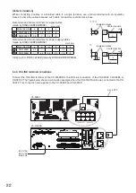
 10. Functional earth terminal [SIGNAL GND]

Hum  noise  may  be  generated  when  external 

equipment is connected to the unit. Connecting 

this terminal to the functional earth terminal of the 

external equipment may reduce the hum noise.

Note: This terminal is not for protective earth.

 11.  Fuse  holders

Requires an AC fuse.

Ratings: 250 V, T6.3A L 

 12. DC output terminals 

   [POWER OUT 19-33V MAX 5A]

DC 33 V max., 5 A max.

Supply DC power to the SX-2000SM or VX-2000 

or  other  DC-operated  devices  except  power 

amplifiers.

 13. DC output terminal

   [POWER OUT 19-33V MAX 25A]

DC 33 V max., 25 A max.

Supplies DC power to power amplifiers or other 

DC-operated devices.

 14.  Fuses

Provided in each DC output.

Type and rating: Blade-Type Fuse 35 A 

Remove the protection cover when replacing the fuse.

 15. Battery connection terminal

   [BATTERY POWER IN]

Connects to the backup sealed lead-acid battery.

Recommended battery: 

2 x Panasonic LC-X1265PG/APG

2 x Panasonic LC-XA12100P

2 x Panasonic LC-XB12100P*

2 x Yuasa NP65-12

2 x Yuasa NPL100-12

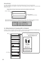
* Compliant with EN54-4

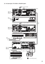
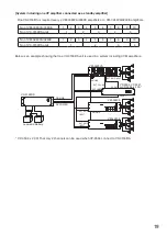
 16. Control connectors [DS LINK IN, OUT]

• DS LINK IN connector

Connects to DS LINK connector of the VX-2000 

system, SX-2000 system, or VM-3000 system.

• DS LINK OUT connector


Connects to DS LINK IN connector of a daisy-

chained unit.


Note:    This connection is required only when 2 

to 4 units are connected to one DS LINK 

connector.

 17.  Fuse holders

The specified AC fuses are incorporated.

Ratings: 250 V, T8A H

 18. AC inlet (AC POWER IN)

Connect to power source of 220 - 230 V AC, 50/60 

Hz using the supplied power cords.

Connect both AC POWER IN to AC mains power 

outlet from single circuit breaker line.

 19. DC output terminal 

   [POWER OUT 24V(16-25V) MAX 0.3A]

DC 24 V max., 0.3 A max.

Supplies DC power to the DC-operated devices 

except power amplifiers.

 20. Temperature sensor connection terminal 

[TEMPERATURE SENSOR]

Detects  the  ambient  temperature  of  the  backup 

battery, and performs temperature compensation 

for  the  charging  voltage.  For  the  installation 

instructions, refer to p. 11.

The temperature sensor has a serial number label 

attached to it. 

When connecting the temperature sensor to this 

terminal, confirm the serial number matches that 

of the VX-3150DS.

10

16

Protection cover

12

17

15

13

11

18

TEMPER

ATURE

SENSOR

24V(16-25V)

POWER OUT

MAX 0.3A

IN

OUT

DS LINK

View with the cover removed

14

20

19

20

Summary of Contents for VX-3150DS

Page 1: ...er Please carefully follow the instructions in this manual to ensure long trouble free use of your equipment 1134 TOA Electronics Europe GmbH Suederstrasse 282 20537 Hamburg Germany 1134 CPR 137 DoP 1...

Page 2: ...Installation 8 4 3 Affixing Declaration of Compliance EN 54 4 Standard 12 5 CONNECTIONS 13 5 1 Connecting the VX 3150DS to VX 2000 System 13 5 2 Connecting the VX 3150DS to SX 2000 System 14 5 3 Conn...

Page 3: ...sconnect the battery and contact your nearest TOA dealer Make no further attempt to operate the unit in this condition as this may cause fire or electric shock If you detect smoke or a strange smell c...

Page 4: ...and negative orientation when connecting the power supply cord Reversed polarity connections will cause damage to the system When the Unit is in Use Use the specified power supply unit for the system...

Page 5: ...ecified value In automatic mode the unit performs battery check every 3 and a half hours When the DS LINK is connected to the VX 2000 system SX 2000 system or VM 3000 system the resistance measurement...

Page 6: ...is the last one of connected units Switches 4 and 5 Set the upper limit value of the internal battery resistance and battery connection cable resistance to be monitored for fault detection Setting sw...

Page 7: ...INK IN OUT DS LINK IN connector Connects to DS LINK connector of the VX 2000 system SX 2000 system or VM 3000 system DS LINK OUT connector Connects to DS LINK IN connector of a daisy chained unit Note...

Page 8: ...battery terminal to prevent shorts between positive and negative terminals Cable end treatment To secure the connection between the battery terminal and cable be sure to use the cable of specified di...

Page 9: ...occurs connect a resistor of 18 k 1 4 W parallel to the batteries Use the specified type of batteries and capacity When batteries are connected together in a series parallel arrangement the inter con...

Page 10: ...G 6 AWG 4 AWG 2 AWG 0 AWG 1 0 80 cm each 130 cm each 190 cm each 275 cm each 20 cm 20 cm 20 cm 20 cm Length 2 m AWG Example of wire length Cable A Cable C Cable B VX 3150DS Battery connection terminal...

Page 11: ...temperature changes when charging the battery It should be mounted on the side of one battery in between 2 batteries using the supplied thermal insulating sheet to avoid ambient temperature change the...

Page 12: ...e g at the upper right side as shown below EN 54 4 VX 3150DS Rack AC POWER BATTERY IN POWER CONNECT CONDITION CHECK CHARGING EN 54 4 Sticker supplied with the VX 3150DS Affix only the upper part of t...

Page 13: ...Y POWER IN 24V MAX 150A POWER OUT 1 2 3 4 5 6 7 POWER OUT 19 33V MAX 25A WARNING Take special care to prevent the battery from being shorted by misconnection of the battery cable If the shore occurs t...

Page 14: ...ble is broken or power fails Note For DC power supply to each component it is possible to use either of POWER OUT 19 33 V MAX 5 A terminal or POWER OUT 19 33 V MAX 25 A terminal SX 2100AI SX 2100AO or...

Page 15: ...MAX 25A WARNING Take special care to prevent the battery from being shorted by misconnection of the battery cable If the shore occurs the unit may fail OUT DS LINK 16 24V MAX 0 3A POWER OUT TEMPERATUR...

Page 16: ...K terminal connections Connect the DS LINK terminal of the VX 3150DS to the DS Link terminal of the SX 2000SM or SX 2100AO The figure below shows a connection example when the VX 3150DS units are conn...

Page 17: ...DS LINK RJ45 male connector AWG 6 AWG 0 1 0 VM 3240VA 3360VA From VX 3150DS From VX 3150DS From VX 3150DS Note Remove the short bar attached at the factory 230 V AC 220 V AC 50 60 Hz 230 V AC 220 V A...

Page 18: ...called VP amplifier System including VM amplifiers only One VX 3150DS is required every 2 VM 3360VA 3360E amplifiers or 3 VM 3240VA 3240E amplifiers Below is an example showing that one VX 3150DS is u...

Page 19: ...3 VM amplifiers No of VM 3360VA 3360E 1 2 3 4 5 6 7 8 9 10 No of VX 3150DS units 1 2 3 4 5 No of VM 3240VA 3240E 1 2 3 4 5 6 7 8 9 10 No of VX 3150DS units 1 2 3 4 VP 3504 x 2 CH That only 2 channels...

Page 20: ...3 4 5 6 7 8 9 10 No of VX 3150DS units 1 2 3 4 5 No of VM 3240VA 3240E 1 2 3 4 5 6 7 8 9 10 No of VX 3150DS units 1 2 3 4 VP 3504 x 2CH That only 2 channels can be used when VP 3504 connect to VX 315...

Page 21: ...e to prevent the battery from being shorted by misconnection of the battery cable If the shore occurs the unit may fail OUT DS LINK 16 24V MAX 0 3A POWER OUT TEMPERATURE SENSOR 8 IN POWER OUT POWER OU...

Page 22: ...cable to a single terminal use a ferrule terminal with an insulation sleeve to crimp the cables because such cable conductors could become loose Recommended ferrule terminals for signal cables made b...

Page 23: ...al AWG 18 AWG 14 0 8 2 0 mm2 Round terminal SX 2000SM SX 2100AI SX 2000AO SX 2100AO SX 2000CI SX 2000CO VX 3004F VX 3008F VX 3016F DC POWER IN 4P removable terminal plug AWG 10 AWG 8 5 5 8 0 mm2 Round...

Page 24: ...e system power Step 1 Turn on the AC power source Step 2 Check the DIP switch s Switch 8 is OFF If not place it to OFF position Step 3 Operate the system normally DIPSW SETTING CHARGE CURRENT 11A 5 5A...

Page 25: ...t Charging Circuit CHARGING Fuse 15 A NO Voltage Checker BATTERY CONDITION BATTERY POWER NC NC NC NC NO Battery Check Switch When battery voltage drops below the reference voltage AC IN Control Connec...

Page 26: ...n the battery data sheets The maximum storage durations are Ambient temperature Maximum time before re charge Less than 20 C 12 months 20 C 30 C 9 months 30 C 40 C 6 months The production date is usua...

Page 27: ...us terminal of the battery to the VX 3150DS check on correct polarity and fixation in the battery cable clamp at the VX 3150DS 2 Connect the minus terminal of the battery with the plus terminal of the...

Page 28: ...arger error will be logged and the Charge LED extinguishes The temperature sensor must not be disconnected during charging of the battery because then the charging voltage becomes high causing the dan...

Page 29: ...l fuse 15 A of the VX 3150DS blown Consult your TOA dealer Either or both fans do not operate Battery Fault Reasons of a battery fault indication 1 resistance increase at the contacts due to corrosion...

Page 30: ...he contact resistance is excluded from the measurement Measure the voltage on each path it may contain a fuse Add these voltages and divide by 5 5 A current The result is the resistance When it exceed...

Page 31: ...otal Applicable Battery Panasonic LC X1265PG APG 65 Ah LC XA12100P 100 Ah LC XB12100P 100 Ah Yuasa NP65 12 65 Ah NPL100 12 100 Ah Control Connector DS LINK IN OUT RJ45 female connector for connecting...

Page 32: ...Minatojima Nakamachi Chuo ku Kobe Hyogo Japan Authorized representative TOA Electronics Europe GmbH Suederstrasse 282 20537 Hamburg Germany Warning This equipment is compliant with Class A of CISPR 32...

Page 33: ......

Page 34: ......

Page 35: ......

Page 36: ...URL https www toa jp 133 02 00250 03...

Reviews: