


21
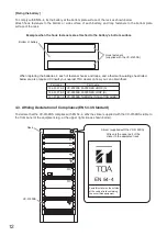
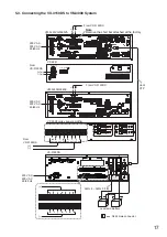
5.4. Connecting the VX-3150DS to VX-3000 System
5.4.1. DC power output terminal connections
Required power is supplied to the system from a single power supply unit.
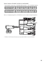
Note
A redundant power system of the VX-3150DS cannot be applied to the VX-3004F, VX-3008F, and VX-3016F.
Note
The VX-3150DS’ “POWER OUT 19 – 33 V MAX 5 A” terminal cannot be used for connecting the Digital amplifier
modules with the VX-3150DS.
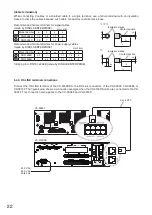
FUSE 35A (POWER OUT)
BATTERY POWER IN
24V
MAX 150A
POWER OUT(-)
1
2
3
4
5
6
7
POWER OUT(+) 19-33V
MAX 25A
WARNING
Take special care to prevent the battery
from being shorted by misconnection
of the battery cable.
If the shore occurs, the unit may fail.
OUT
DS LINK
16-24V
MAX 0.3A
POWER OUT
TEMPER
ATURE
SENSOR
8
IN
POWER OUT(-)
POWER OUT(+) 19 – 30V MAX 25A
3
1
d
c
a
b
h
g
e
f
b f
e
a
d h
g
c
VX-3150DS
4P removable terminal plug
(supplied with the VX-3004F, VX-3008F, and VX-3016F)
(DC power input terminal)
(DC power input terminal)
VX-3004F, VX-3008F, or VX-3016F
VX-3004F, VX-3008F, or VX-3016F
This figure represents the VX-3004F.
This figure represents the VX-3016F.
Amplifier DC power input terminal
(VX-015DA, VX-030DA, or VX-050DA
Digital power amplifer module)
Amplifier DC power input terminal (VX-015DA, VX-030DA, or VX-050DA)
+
+
-
-
230 V AC
220 V AC
50/60 Hz
Cable: AWG 18 – AWG 14


