


4
• When connecting multiple appliances to a single
power socket through a multi-outlet power strip, a
total current consumption of the appliances must
not exceed the allowable current capacity of the
power socket.
Failure to observe this instruction may result in a
fire or electric shock.
• When 2 or more AC power cords are connected to
a multi-outlet power strip, never remove the power
strip from a power source.
• Avoid installing the unit in humid or dusty locations,
in locations exposed to the direct sunlight, near the
heaters, or in locations generating sooty smoke
or steam as doing otherwise may result in fire or
electric shock.
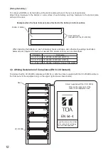
• System units (except remote microphones) are
designed exclusively to be mounted in an equipment
rack. Be sure observe the following instructions
when rack-mounting the unit. Failure to do so may
cause a fire or personal injury.
· Install the equipment rack on a stable, hard floor.
Fix it with anchor bolts or take other arrangements
to prevent it from falling down.
· The supplied rack-mounting screws can be used
for the TOA equipment rack only. Do not use them
for other racks.
• Note correct polarity (positive and negative
orientation) when connecting the power supply
cord. Reversed polarity connections will cause
damage to the system.
When the Unit is in Use
• Use the specified power supply unit for the system.
Note that the use of other power supply unit may
cause a fire.
• Make sure to observe the following handling
precautions so that a fire or personal injury does
not result from leakage or explosion of the battery.
· Do not short, disassemble, heat nor put the battery
into a fire.
· Avoid using both new and old batteries together.
· Never charge batteries of the type which are not
rechargeable.
· Do not solder a battery directly.
· Be sure to use the specified type of batteries.
· Note correct polarity (positive and negative
orientation) when connecting a battery to the unit.
· Avoid locations exposed to the direct sunlight,
high temperature and high humidity when storing
batteries.
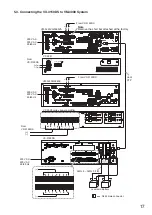
2. FEATURES
• Automatically switches to the backup power supply when the AC Mains power supply is interrupted.
• Detects charging circuitry or battery failures, and transmits failure signals to the DS LINK of the TOA Voice
Evacuation Systems (VX-2000, SX-2000, and VM-3000).
• Keeps a 2 x 12 V sealed lead-acid battery charged while maintaining temperature compensation for the
charging voltage.
• Automatically disconnects the battery if its voltage reaches a discharge final level.


