


31
Power Source
220 – 230 V AC, 50/60 Hz
Power Consumption
1460 W max. in total (at rated output with charging)
460 W max. (EN60065)
DC Power Output (AC
mode)
Rated output: 1140 W (total DC power output)
Peak output: 1280 W (total DC power output)
Current Specification
Maximum output current from the battery : 25 A
Rated maximum continuous output current, I max. a : 25 A
Rated maximum short duration output current, I max. b : 25 A
Rated minimum output current, I min.: 0 A
Ripple Voltage at I max. b: 4 V max.
DC Power Output
8 x 31 V (19 – 33 V) 25 A max. each, M4 screw terminal,
distance between barriers: 11 mm
3 x 31 V (19 – 33 V) 5 A max. each, removable terminal block (3 x 2 pins)
1 x 24 V (16 – 25 V) 0.3 A max., removable terminal block (1 x 2 pins)
Charging Method
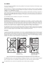
Temperature compensated trickle charging
Charging Output
Voltage
27.3 V ± 0.3 V (at 25°C)
Temperature correction coefficient: –40 mV/°C
Battery Connection
1 pair of positive and negative terminals
Applicable cable diameter: AWG 6 − AWG 0 (AWG 1/0) (16 – 50 mm
2
)
Line resistance within:
4 mΩ/total
Applicable Battery
Panasonic: LC-X1265PG/APG (65 Ah), LC-XA12100P (100 Ah),
LC-XB12100P* (100 Ah)
Yuasa:
NP65-12 (65 Ah), NPL100-12 (100 Ah)
Control Connector
(DS LINK IN/OUT)
RJ45 female connector for connecting the system and cascade connection
Shielded twisted-pair straight cable (TIA/EIA-568A standard)
Type of control signal: Battery check, AC power status, DC Power status,
charging circuit failure, battery failure, and communication
Panel Indicator
AC power IN:
Green LED
Charging:
Green LED
Battery power:
Green LED
Battery connect: Green LED
Battery condition: Green LED
Operating Temperature
–5 to +45°C
Operating Humidity
90% RH or less (no condensation)
Finish
Panel: Surface-treated steel plate, black (30% gloss), paint
Dimensions
482 (w) x 132.6 (h) x 400.5 (d) mm
Weight
9 kg
Fuse Rating
Blade fuse (35 A), Fuse (T8A H), Fuse (T6.3A L)
Fuse T8A H ......................................................... 1
Fuse T6.3A L ....................................................... 2
Blade fuse (35 A) .................................................. 2
Rack mounting screw
(with plain washer) 5 x 12 ..................................... 4
Power cord (2 m) ................................................. 2
Fastener hook ..................................................... 4
Fastener loop ...................................................... 4
Removable terminal plug (2 pins) ........................ 3
Sticker (Declaration of compliance) ..................... 1
CAT5 STP cable (3 m) ......................................... 1
Thermal insulating sheet ..................................... 1
Ferrite cable clamp .............................................. 1
Note: The design and specifications are subject to change without notice for improvement.
10. SPECIFICATIONS
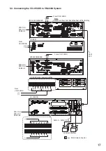
• Accessories


