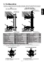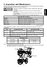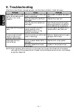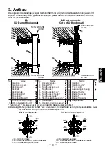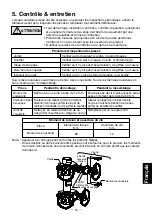
4. Proper Installation
CAUTION
• Installation, inspection, maintenance, repairs, disassembly, adjustment
and valve opening/closing should be carried out only by trained
maintenance personnel.
• Take measures to prevent people from coming into direct contact with
product outlets.
• Install for use under conditions in which no freeze-up will occur.
• Install for use under conditions in which no water hammer will occur.
1. Before installing the product, blow out the inlet
piping to remove any piping scraps, dirt and oil.
Close the inlet valve after blowdown.
2. Before installation, be sure to remove all
protective seals.
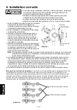
3. Prepare a mounting stand. The mounting stand
should be less than 160mm (6 ") wide (the
face to face distance between station
connections). If a wider mounting stand is used,
it may interfere with any steam trap station
connected to the manifold.
4. Using M12 threaded bolts, attach the manifold
to the mounting stand (figure 1). Install the
manifold vertically with the raised “TLV”
lettering on the body right-side up and
horizontal.
Note
: If the manifold is to be mounted in some way other than as described here, be sure to
consider and secure sufficient space for the installation, operation and maintenance of
required steam traps and valves.
5. Complete the installation by installing the required steam traps and valves. For steam
applications, install a stop valve at the steam inlet, and a steam trap and stop valve at the drain
connection. For condensate applications, install stop valves at the condensate outlet and
blowdown connections, and a trap station with a trap unit or a steam trap and stop valve at
each station connection. For the proper installation of trap stations, steam traps and/or valves,
refer to the separate instruction manuals of each product.
6. Open the inlet and the outlet valves and verify proper operation. If there is a problem,
determine the cause using the “Troubleshooting” section in this manual.
16
5
/
Note for Screwed Connections
: There may be clearance problems when installing traps and
valves with threaded connections. To prevent any obstructions, such as valve handles contacting
products installed on lines above or below, offset each line slightly. Install all short lines first, then
longer lines (figure 2). Offsetting lines is not necessary when installing products with socket
welded connections.
Mounting
Stand
M12 Thread Bolt
& Nut
16
5
/
160 mm
(6 ")
Figure 1
Mounting Stand
Width
Install short lines first
Install long lines last
Figure 2
English
― 7 ―
Summary of Contents for M12
Page 19: ... 18 ...
Page 26: ... 25 ...


