


14
15
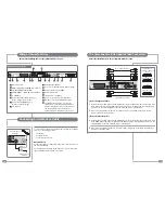
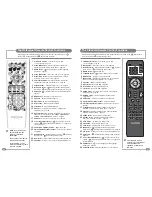
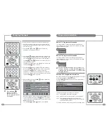
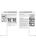
IR Links, RJ12 and RS-232 Connectors
RS-232
RJ12
IR Link
a In
In
Out
IR Link In
The IR Link In socket enables the Mirage
to receive the IR code from an external
IR receiver.
The RJ12 Connector
The RJ12 connector enables the Mirage to
integrate with Interactive Hotel TV systems.
IR Link Out
Codes received by the IR receiver inside the Mirage
can be relayed to an IR emitter via the IR Link Out
socket.
The RS-232 Port
The RS-232 control port enables the Mirage to be
controlled from home automation control systems.
The plug for the IR Out is a ‘mono’ 3.5 mm jack plug.
The plug for the IR In is a ‘stereo’ 3.5 mm jack plug.
The Mirage infrared remote control uses the NEC protocol.
For a full listing of the IR remote control codes see page 55.
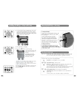
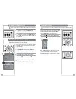
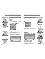
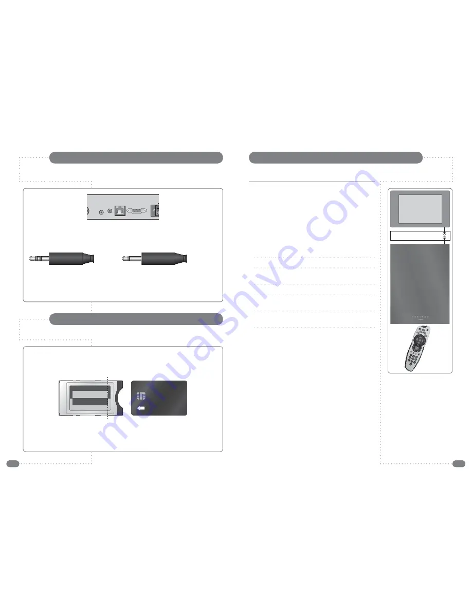
The Common Interface (CI) Port
If a Conditional Access Module (CAM) is being used to add channels to the Mirage the CAM should be
inserted into the CI Port of Mirage
with the power disconnected
.
Take a note of the Smart Card’s serial number and follow the CAM/Smart Card manufacturer’s
instructions to insert the Smart Card into the CAM and access the service.
The Smart Card should be activated in accordance with its service provider’s instructions before the
screws are tightened in the fixing points and the screw caps are inserted.
See page 29 for additional CI/Smart Card information.
The dotted line indicates the edge of the metalwork when a CAM is correctly inserted.
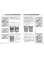
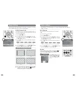
INSERT
The connection to the antenna connectors on the Mirage and the
Sky™ box must be made with both the Mirage and the Sky™ box
disconnected from the mains supply. Use good quality coax cable
either directly from the RF2 outlet of the Sky™ box or the outlet of a
Remote-Link amp in an uninterrupted run.
Once the connections have been made, the Sky™ box must be
setup to supply power from the RF 2 socket as detailed below.
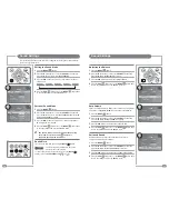
To set-up the Sky™ box to work with the Mirage the Sky™
remote control must be used via the main TV (TV 1).
1
On the Sky™ remote control press
SERVICES
to show the
SERVICES menu.
2
Press the
4
button for the SYSTEM SETUP menu.
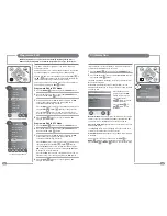
3
Press the
0
button, then the
1
button, then the
select
button, in
sequence, to display the INSTALLER SETUP menu.
4
Press the
4
button to select RF OUTLETS.
5
Press the
down
arrow to select RF Outlet Power Supply and
press the
left
or
right
arrows to change the setting to ON.
6
Press the
down
arrow to select Save New Settings and press
select
to save the settings.
7
Press the
sky
button to return to the previously viewed channel.
Sky™ Remote Control Link Setup
If the Mirage is used with a Sky™ box, the channel can be changed on the Sky™ box using the
Sky™ remote control via the remote control sensor on the Mirage.
Sky™ box
RF 1
RF 2
TV 1