


8
ILM for rothe erde
®
slew drives
9
If possible, the slew drive should be installed in the vertical
rotation axis.
The mounting surface must be free of anti-corrosion agents.
An alkaline cleaning agent can be used to clean the contact
surface.
Note:
The preservative can easily be removed with, for example, a
biodegradable alkaline cleaning agent.
Warning:
Do not let the cleaning agent touch the sealing or raceway!
Do not paint the sealing!
The slew drive must be installed on a level,
oil/grease-free surface of bare metal.
When connecting the slew drive to the connecting structure, check
that the fastening holes (slew drive/connecting structure) match.
If the fastening holes do not match, the slew drive may warp when
the bolts are tightened. In the installation process, first connect the
housing mounting surface to the connecting structure.
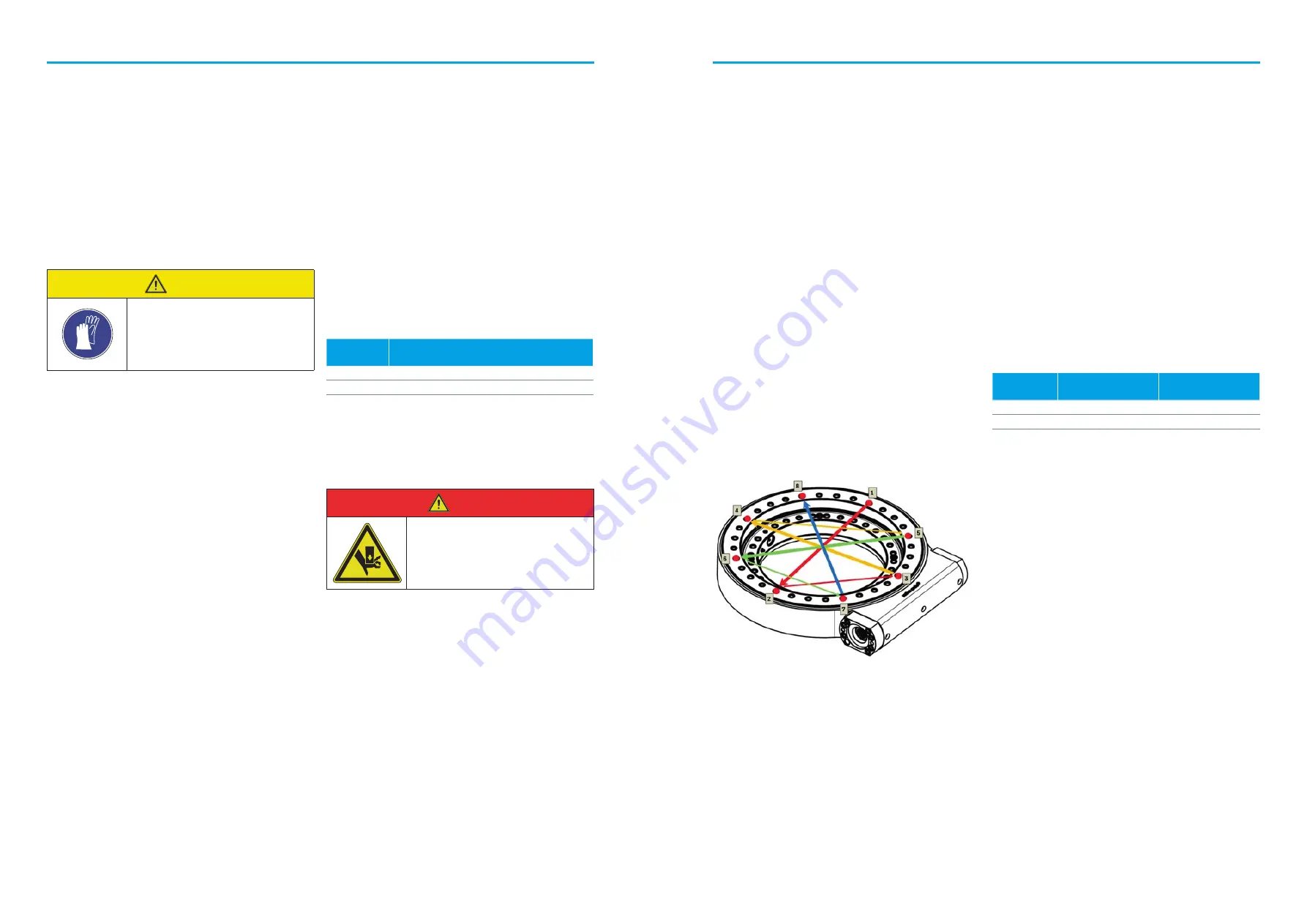
The slew drive’s fastening bolts must be of strength grade
10.9 and hand tightened. Please use the specified number and
diameter of bolts. Carefully tighten the bolts diagonally using
a suitable tool (see Figure 1).
Warning:
Do not allow peaks to form in small sectors, i.e. from 0°–180° the
curve should only rise and fall once evenly.
Hardness gap: The unhardened areas – “hardness gap”
(stamped “S”) – of the ball slewing bearing must be arranged
in the load-neutral area.
Table 3: Permitted deviation from levelness of contact surfaces
under DIN EN ISO 1101
Table 4: Preload forces and tightening torques from VDI 2230
Figure 1: Correct order for tightening fastening bolts
WARNING
Preservatives may
cause skin irritation
• Wear gloves when removing
• Please follow the manufacturer’s
instructions
Ball track Ø
Deviation from levelness under
DIN EN ISO 1101
up to 500 mm
0.10 mm
up to 1000 mm
0.15 mm
Bolts
10.9
Preload force
[kN]
Tightening torque
M16
115.7
338
M20
181
661
DANGER
Danger of crushing when depositing the
load
• Inspect the site before depositing
• Be aware of co-workers
Please check that the contact surfaces for the slew drive are level.
The maximum permitted deviation from levelness under DIN EN
ISO 1101 is given in Table 3.
Ball track Ø can be found in the model specifications.
For example: SE 0244-L => ball track Ø 244 mm
After the first 20% of the bolts are tightened diagonally, all bolts
must be tightened. As tightening the bolts affects the neighboring
bolts, this should be done in at least two passes.
Warning:
Please check the bolt length in advance. At least 6 free thread
turns must be available in the part of the bolt that is loaded (thread
seat) to guarantee the minimum bolt penetration.
The interface pressure under the bolt head/nut may not exceed the
permitted limits. If the interface pressure limit is exceeded, wash-
ers of suitable size and hardness must be used (see section
“Bolts” in the rothe erde
®
Large Diameter Slewing Bearing catalog
or download it at https://www.thyssenkrupp-rotheerde.com/en/
downloads/brochures-and-catalogues)
The above tightening torque assumes threads and nuts/head con-
tact surfaces have been lightly oiled and that bolts and nuts do not
have treated surfaces (total µ ges. = 0.140).
1.3.3 Operating
temperature
The temperature range for the slew drive extends from -20°C to
60°C, assuming an even temperature distribution. If temperatures
fall outside the permitted temperature range, steps must be taken
to stay within it.
Please contact thyssenkrupp rothe erde Germany GmbH.
1.3.4 Duty cycle
Slew drives are designed for short-lasting loads. Overly long duty
cycles lead to temperature increases and premature breakdown of
the slew drive. A full load duty cycle of 10% of a minute must be
followed by an appropriate cool-down period.
1.3.5 Start-up
The slew drive must be fully bolted together when started up.
Please ensure that the slew drive cannot be damaged by current
flow or equalization of potential during installation and operation.
1.3 Installation
1.3.1 Preparation
1.3.2 Bolts


