PTR306 / PTR306B Recoaters with Linear Proof Testers
Chapter 6: Controlling the PTR306/PTR306B
Rev D, October 2, 2020
Page 19
Recoating (PTR306B)
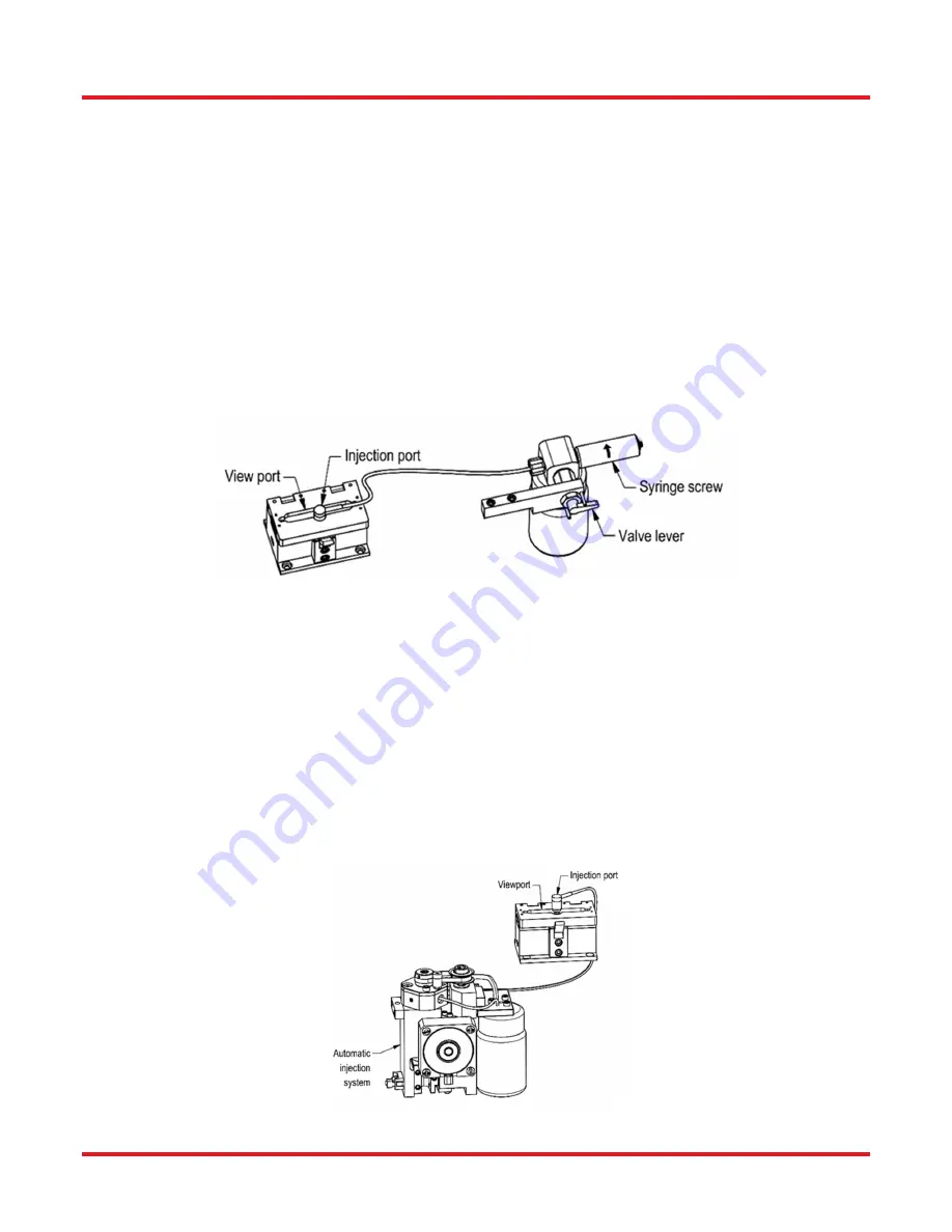
Make sure that the selection lever is in the inject position (lever up). Once the fiber has been captured in the recoat
mold assembly, the injection syringe should be screwed in (turned clockwise) to inject the UV acrylate material into
the mold cavity. The material will flow from the injection port, down a shallow channel, into the recoat cavity. The
syringe should be turned slowly to give the material time to flow smoothly along the injection path.
Use the viewport in the recoat top to watch the material flow into the mold. Continue turning the injection syringe
until the acrylate material reaches both coating interfaces of the exposed section of fiber. A slight migration of the
acrylate material outside of the injection path between the two mold plates can be expected. The bottom mold plate
has an optical coating that prevents this material from curing and forming a characteristic mold flashing. Excessive
flashing flow indicates that the plates did not mate flush together. This is generally caused by dirt particles on the
mold plates and/or by trying to recoat a fiber that has a larger coating diameter than the recoat mold.
Note: If the syringe end of travel is reached during the injection process, the syringe can be re-filled mid-process by
positioning the selection lever to the fill position (lever down) and un-screwing (turn counterclockwise) the syringe
screw. Once filled, re-position the selection lever to the inject position (lever horizontal) and continue injecting
material into the mold.
Figure 14 Remote Manual Recoat Injection
Recoating (PTR306)
Once the fiber has been captured in the recoat mold assembly, activate the injection process with one of the
available controllers. This will activate the injection pump and dispense the specified amount of recoat material.
Use the viewport in the recoat top to watch the material flow into the mold. If the flow of recoat material does not
reach the existing coating interface, inject additional material until the recoat material has reached the coating
interface.
A slight migration of the acrylate material outside of the injection path between the two mold plates can be expected.
The bottom mold plate has an optical coating that prevents this material from curing and forming a characteristic
mold flashing. Excessive flashing flow indicates that the plates did not mate flush together. This is generally caused
by dirt particles on the mold plates and/or by trying to recoat a fiber that has a larger coating diameter than the
recoat mold.
Figure 15 Automatic Recoat Injection
Summary of Contents for PTR306
Page 1: ...PTR306 PTR306B Manual Fiber Recoater with Linear Proof Tester User Guide...
Page 39: ...PTR306 PTR306B Recoaters with Linear Proof Testers Chapter 10 Appendix Page 36 TTN090913 D02...
Page 41: ...PTR306 PTR306B Recoaters with Linear Proof Testers Chapter 10 Appendix Page 38 TTN090913 D02...
Page 43: ...PTR306 PTR306B Recoaters with Linear Proof Testers Chapter 10 Appendix Page 40 TTN090913 D02...
Page 48: ...www thorlabs com...


