45
K-Cube Position Aligner
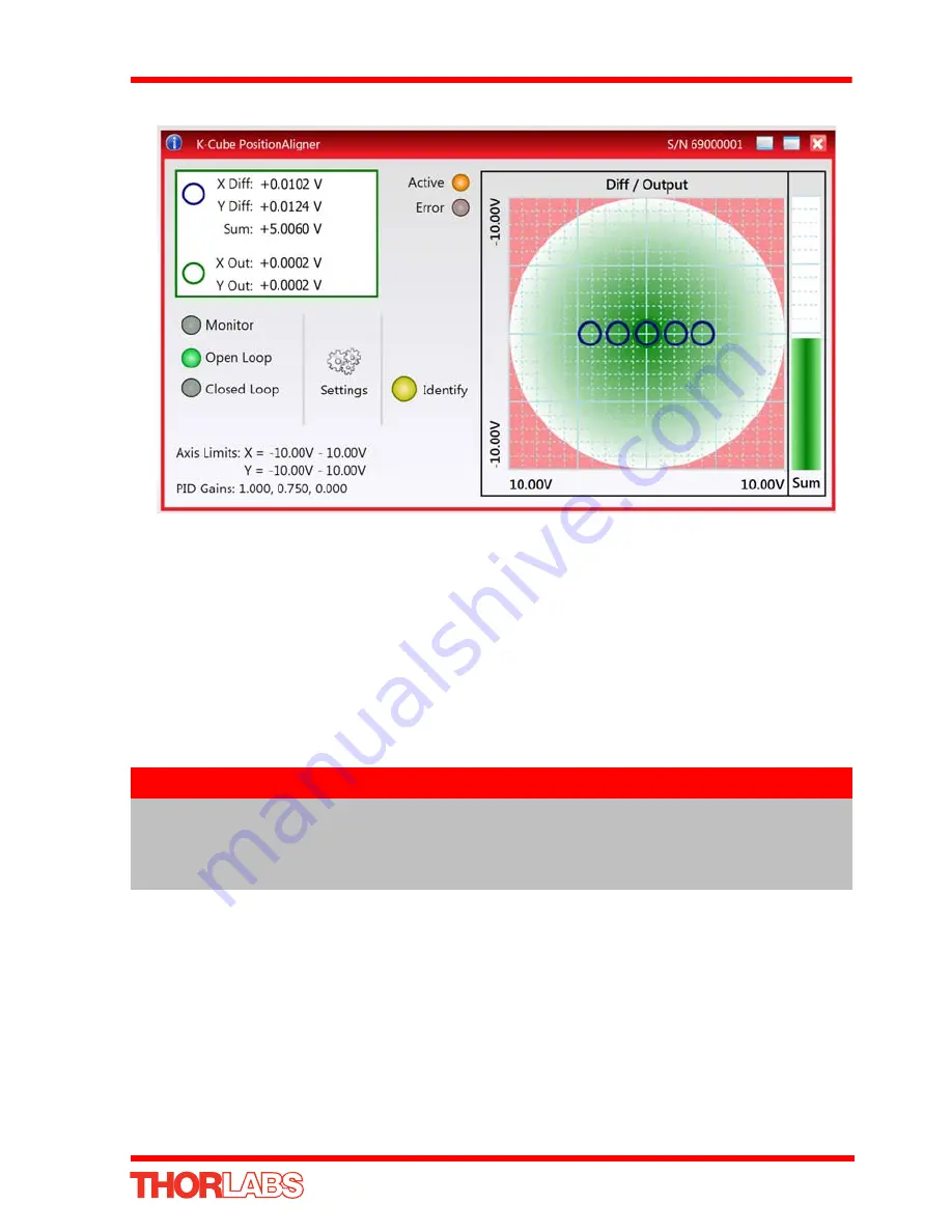
Fig. 5.8 X-axis Position Demand Sense Check
6) Check that the piezo controller connected to the Y DIFF connector, is driving the
Y-axis piezo actuator. Turn the control knob on the piezo controller to increase the
piezo drive voltage. The laser beam should move along the Y axis with very little
X axis movement. If the beam moves in the X-axis (or di agonally), the piezo
controller is connected to the wrong actuator.
7) When the Y-axis piezo voltage is increased, if the spot moves towards the top, the
demand sense is positive. If the sp ot moves towards the bottom, the demand
sense is negative.
8) Press the CLOSED LOOP button on the GUI panel to select ‘Closed Loop’ mode,
i.e. the CLOSED LOOP LED is lit.
The position aligner unit now takes over the alignment, and controls the piezo
units to drive the piezo mirror to direct the laser beam to the central position. The
beam position within the sensor array is indicated by the ‘Grid’ display.
9) Depending on the position of other components in the system, it is possible that
the travel range of the piezo actuators driving the mirror is not sufficient to position
the beam on the detector array. In this case, the piezos should be centered and
the actuators on the o ther turning mirrors should be adjusted to reposition the
beam as follows:
Note
The default settings for the Position Demand Sense is ‘Positive’, which is
correct for the set up shown in Fig. 5.2. If the check described at item (7)
shows a negative demand sense, then it will be necessary to change the
Position Demand Sense
parameter in the Settings panel - see Section 6.2.


