41
K-Cube Position Aligner
13)Click ‘OK to save the settings.
14)On the GUI panel, turn the ‘Output’ control to give a reading of 0V on the display.
15)Click the ‘Settings’ button on GUI of the Piezo Driver fitted in bay 3. The Settings
panel is displayed
16)Make the following parameter settings, as shown in Fig. 5.3
Feedback Loop Mode -
Select
Open Loop
Output Voltage Range -
For the ASM003 mirror shown in Fig. 5.2
,
set
75V
, (for
other piezo mirrors, set 75V, 100V or 150V whichever is applicable)
.
Input Source -
Select
So External Signal
Analogue Input Mode -
Select
Analogue Channel 1
17)It is advisable to click the ‘Persist Settings To Hardware’ box. These settings will
then be loaded on each power up cycle
18)On the position aligner GUI, click the ‘Settings’ button to disp lay the Se ttings
panel.
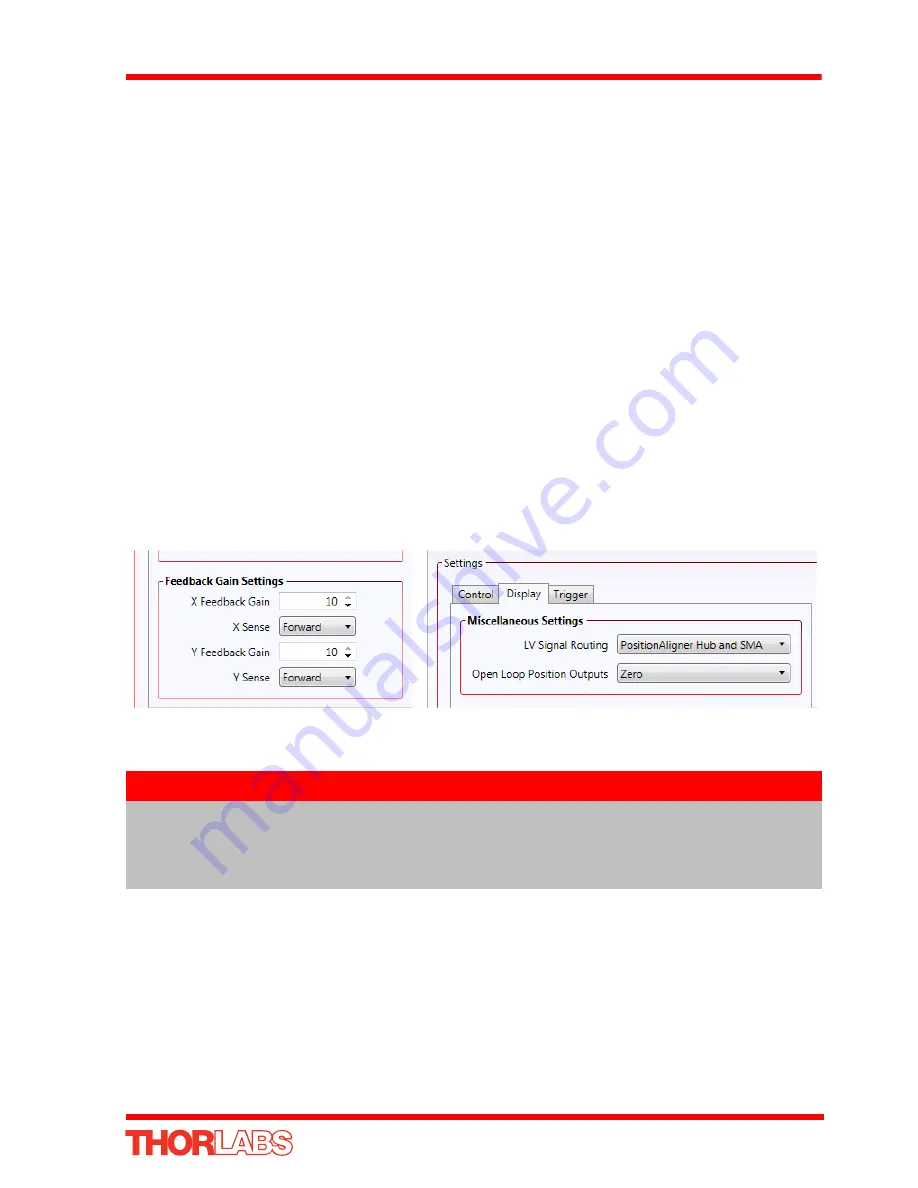
19)Click the Control tab and set the
X & Y Feedback Sense
to
Forward
as shown in
Fig. 5.4.
20)Click the Display tab and set the
LV Signal Routing
parameter to
PositionAligner
Hub and SMA
, as shown in Fig. 5.4..
Fig. 5.4 KPA101 Settings Panel - Hub Operation
21)It is advisable to click the ‘Persist Settings To Hardware’ box. These settings will
then be loaded on each power up cycle
22)Click ‘OK to save the settings.
Note
When signals are routed via the hub, the YDIFF signal is routed via
Channel 1 and XDIFF is routed via channel 2. It is important to set
correctly the hub channels for the associated piezo controllers and to
make correct connections to the X-axis and Y-axis piezo actuators.


