background image

Rev G Apr 2019

Page 9

Chapter 4 Operation

5) The stage can now be moved using the Pot, GUI panel, or by setting commands

to move each axis by relative and absolute amounts – see the handbook supplied

with the KBD101 controller, and the helpfile supplied with the software for more

information

6) The stage is shipped already loaded with default parameter settings, which should

give  satisfactory  performance  in  most  cases.  However,  depending  on  the

application, it may be necessary to adjust the PID loop parameter settings to fine

tune the response - see the following pages for more information.

4.2 Using the Kinesis software

1) If it is not already running, start the Kinesis software - Start/Programs/Thorlabs/

Kinesis/Kinesis

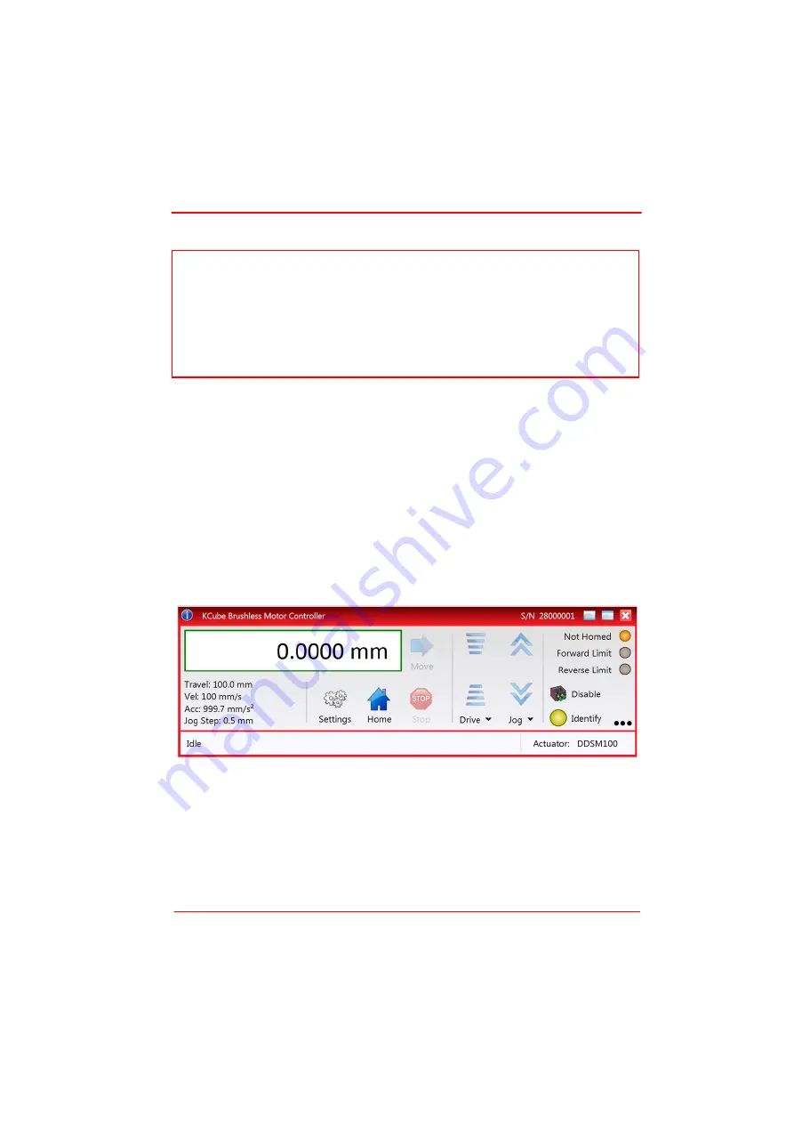
The software reads in the stage and controller information on boot up and the GUI

panel shown below is displayed..

Fig. 4.1   Kinesis GUI screen

Note

The need for homing comes from the fact that on power up the motor (stage) is at a 

random position, so the value of the position counter is meaningless. Homing 

involves moving the motor to a known reference marker and resetting the position 

counter to the associated absolute value. This reference marker can be one of the 

limit switches or can be provided by some other signal. The DDSM series stages use 

an electronic reference marker and therefore the limit switches are not used for 

reference.

Summary of Contents for DDSM100

Page 1: ...HA0266T DDSM100 Direct Drive Translation Stage User Guide Original Instructions...

Page 2: ...is Configurations 6 3 3 Electrical Connections 7 Chaper 4 Operation 8 4 1 General 8 4 2 Using the Kinesis software 9 4 3 Using the APT software 12 4 4 Position Error Messages 15 4 5 Transportation 15...

Page 3: ...ved linear bearing provides superior rigidity and linearity with excellent on axis accuracy This backlash free operation coupled with high resolution closed loop optical feedback ensures a minimal bid...

Page 4: ...Cautions and Notes throughout this handbook and where visible on the product itself The following safety symbols may be used throughout the handbook and on the equipment itself Warning Risk of Electri...

Page 5: ...d fluid to enter the internal mechanism When bolting the stage to the work surface high tightening torque of the attachment bolts can result in an increased resistive force on the moving platform This...

Page 6: ...sary see Section 3 2 for more details When bolting the stage to the work surface high tightening torque of the attachment bolts can result in an increased resistive force on the moving platform This i...

Page 7: ...ot flat Care should be taken when bolting the stage to the worksurface to ensure that the base plate does not warp which could cause stiffness to be experienced in the bearing rails Shims should be fi...

Page 8: ...to the lower stage 2 Using the two M3 bolts supplied fit the upper stage to the adapter plate Caution During item 1 use the bolts supplied If these are not available do not use bolts longer than 3 32...

Page 9: ...connections Pin out information for the connector on the motor lead is detailed below Fig 3 4 MOTOR flying lead pin identification Pin Description Pin Description 1 Quadrature A 9 GND 2 Quadrature A...

Page 10: ...Brushless DC Motor K Cube For full compatibility the controller should have Firmware version 1 0 1 or higher The Firmware version is displayed on start up see the associated controller manual for more...

Page 11: ...formation 4 2 Using the Kinesis software 1 If it is not already running start the Kinesis software Start Programs Thorlabs Kinesis Kinesis The software reads in the stage and controller information on...

Page 12: ...loads up to the 250 g 0 55 lb maximum at speeds up to 500 mm s However depending on the load being driven and the speed duty cycle of the particular application it may be necessary to further optimiz...

Page 13: ...the stages are mounted in an XY configuration Table 4 1 DDSM100 Position Loop Parameter Adjustment Guidelines Load Range g Derivative Derivative Time Output Gain 0 to 250 4500 5 4000 250 to 500 5160...

Page 14: ...up to 500 mm s However depending on the load being driven and the speed duty cycle of the particular application it may be necessary to further optimize the Position PID loop settings See Table 4 1 fo...

Page 15: ...ick OK This will ensure that the same parameter settings will be loaded next time the unit is powered up even in the absence of a PC Depending on the shape of the mass and the accelerations and veloci...

Page 16: ...osition PID Settings Summary Stage overshoots the intended position reduce the integral term and increase the derivative and proportional terms Stage fails to attain final position increase the integr...

Page 17: ...on and the stage is moved manually at high speeds it is possible to exceed this limit If the KBD101 controller is subsequently used again to move the stage the incorrect encoder reading will cause inc...

Page 18: ...coder scale should be cleaned periodically with isopropyl alcohol and a cotton bud as follows 1 Move the top platform to one end of its travel 2 Moisten a cotton bud with Isopropyl alcohol 3 Insert th...

Page 19: ...mensions Mid Travel 195 mm x 57 mm x 35 mm 7 7 x 2 25 x 1 38 Weight with cables 0 72 kg 1 6 lbs Note The default tuning parameters can be changed to optimise settling times for a specific load see Sec...

Page 20: ...rrent the motor can draw without exceeding temperature limits d The absolute maximum current without exceeding temperature limits Parameter Value Magnetic Pitch 30 mm Maximum Continuous Current c 1 2...

Page 21: ...harmful interference when the equipment is operated in a commercial environment This equipment generates uses and can radiate radio frequency energy and if not installed and used in accordance with th...

Page 22: ...Page 20 23108 D02 DDSM100 Direct Drive Translation Stage 7 2 CE Certification...

Page 23: ...Rev G Apr 2019 Page 21 Chapter 7 Regulatory...

Page 24: ...ct Thorlabs for more information Waste treatment is your own responsibility End of life units must be returned to Thorlabs or handed to a company specializing in waste recovery Do not dispose of the u...

Page 25: ...www thorlabs com...

Reviews: