


Page 10
23108-D02
DDSM100 Direct Drive Translation Stage
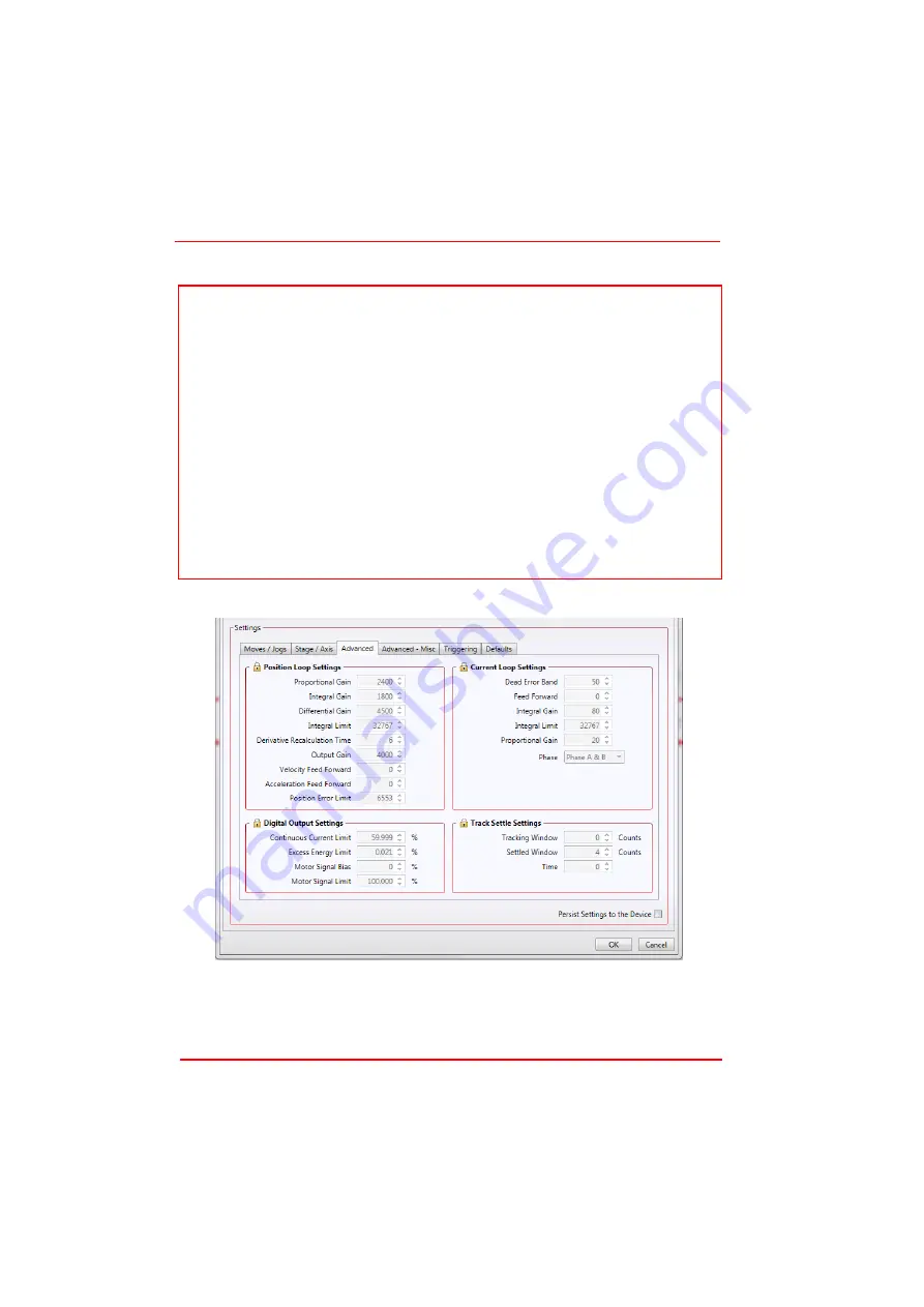
2) Click the Settings button on the GUI to display the Settings panel, then select the
‘Advanced’ tab.
Fig. 4.2 Advanced Control Loop Settings
3) Create a Custom Settings Group (see the Kinesis helpfile for more information)
and then adjust the acceleration and PID settings to fine tune the control loop for
your application - see Table 4.1 and Table 4.2 for more information.
Note
The MOTOR DRIVE connectors for each channel/axis contain an EEPROM, which
stores the factory default settings for the set up parameters. When the stage is
connected, these settings are loaded into the controller on start up, and are tuned
for loads up to the 250 g (0.55 lb) maximum, at speeds up to 500 mm/s.
However, depending on the load being driven and the speed/duty cycle of the
particular application, it may be necessary to further optimize the Position PID loop
settings. See Table 4.1 for suggested PID settings at a given load.
If problems are encountered (e.g. stability of the closed loop position control, lost
motion or incomplete moves) the position loop PID parameters should be adjusted
to tune the stage for the given application. Normally, only minor adjustment of the
Proportional, Integral and Derivative parameters should be necessary, and some
trial and error will be required before the ideal settings for a specific application are
achieved. In cases where further adjustment of the control loop parameters is
required, the following guidelines are provided in order to assist in the tuning
process.


