THORLABS DDSM100 User Manual Download Page 6

Page 4

DDSM100 Direct Drive Translation Stage

Chapter 3 Installation

3.1 Unpacking

3.2 Mounting

3.2.1 Vertical Mounting

3.2.2 General

Note

Retain the packing in which the unit was shipped, for use in future transportation.

Caution

Once  removed  from  its  packaging,  the  stage  can  be  easily  damaged  by

mishandling.  The  unit  should  only  be  handled  by  its  base,  not  by  any

attachments to the moving platform.

Warning

The stage is not suitable for mounting in a vertical (Z-axis) configuration.
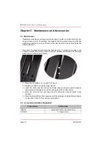
Caution

The  straightness  of  motion  of  the  stage  could  be  affected  if  the  mounting

surface  is  not  flat.  Care  should  be  taken  when  bolting  the  stage  to  the

worksurface, to ensure that the base plate does not warp. Shims should be

fitted as necessary - see Section 3.2. for more details.
When  bolting  the  stage  to  the  work  surface,  high  tightening  torque  of  the

attachment  bolts  can  result  in  an  increased  resistive  force  on  the  moving

platform. This in turn can lead to degraded performance and may require the

PID parameters to be adjusted. 
As a general guide, 70 N.cm is a recommended nominal torque when tightening

the attatchment bolts.
High drag forces can adversely affect phase initialization, homing, positioning

accuracy  and  general  reliability.  Take  care  to  minimize  drag  caused  by

attachments  to  the  moving  platform  (cables,  tubing,  electrical  wiring),

especially when the stage is changing direction.
When mounting the stage close to other equipment, ensure that the travel of the

moving  platform  is  not  obstructed.  If  equipment  mounted  on  the  moving

platform is driven against a solid object, damage  to  the internal mechanism

could occur. The range of travel is 100 mm (3.94“).

Summary of Contents for DDSM100

Page 1: ...HA0266T DDSM100 Direct Drive Translation Stage User Guide Original Instructions...

Page 2: ...is Configurations 6 3 3 Electrical Connections 7 Chaper 4 Operation 8 4 1 General 8 4 2 Using the Kinesis software 9 4 3 Using the APT software 12 4 4 Position Error Messages 15 4 5 Transportation 15...

Page 3: ...ved linear bearing provides superior rigidity and linearity with excellent on axis accuracy This backlash free operation coupled with high resolution closed loop optical feedback ensures a minimal bid...

Page 4: ...Cautions and Notes throughout this handbook and where visible on the product itself The following safety symbols may be used throughout the handbook and on the equipment itself Warning Risk of Electri...

Page 5: ...d fluid to enter the internal mechanism When bolting the stage to the work surface high tightening torque of the attachment bolts can result in an increased resistive force on the moving platform This...

Page 6: ...sary see Section 3 2 for more details When bolting the stage to the work surface high tightening torque of the attachment bolts can result in an increased resistive force on the moving platform This i...

Page 7: ...ot flat Care should be taken when bolting the stage to the worksurface to ensure that the base plate does not warp which could cause stiffness to be experienced in the bearing rails Shims should be fi...

Page 8: ...to the lower stage 2 Using the two M3 bolts supplied fit the upper stage to the adapter plate Caution During item 1 use the bolts supplied If these are not available do not use bolts longer than 3 32...

Page 9: ...connections Pin out information for the connector on the motor lead is detailed below Fig 3 4 MOTOR flying lead pin identification Pin Description Pin Description 1 Quadrature A 9 GND 2 Quadrature A...

Page 10: ...Brushless DC Motor K Cube For full compatibility the controller should have Firmware version 1 0 1 or higher The Firmware version is displayed on start up see the associated controller manual for more...

Page 11: ...formation 4 2 Using the Kinesis software 1 If it is not already running start the Kinesis software Start Programs Thorlabs Kinesis Kinesis The software reads in the stage and controller information on...

Page 12: ...loads up to the 250 g 0 55 lb maximum at speeds up to 500 mm s However depending on the load being driven and the speed duty cycle of the particular application it may be necessary to further optimiz...

Page 13: ...the stages are mounted in an XY configuration Table 4 1 DDSM100 Position Loop Parameter Adjustment Guidelines Load Range g Derivative Derivative Time Output Gain 0 to 250 4500 5 4000 250 to 500 5160...

Page 14: ...up to 500 mm s However depending on the load being driven and the speed duty cycle of the particular application it may be necessary to further optimize the Position PID loop settings See Table 4 1 fo...

Page 15: ...ick OK This will ensure that the same parameter settings will be loaded next time the unit is powered up even in the absence of a PC Depending on the shape of the mass and the accelerations and veloci...

Page 16: ...osition PID Settings Summary Stage overshoots the intended position reduce the integral term and increase the derivative and proportional terms Stage fails to attain final position increase the integr...

Page 17: ...on and the stage is moved manually at high speeds it is possible to exceed this limit If the KBD101 controller is subsequently used again to move the stage the incorrect encoder reading will cause inc...

Page 18: ...coder scale should be cleaned periodically with isopropyl alcohol and a cotton bud as follows 1 Move the top platform to one end of its travel 2 Moisten a cotton bud with Isopropyl alcohol 3 Insert th...

Page 19: ...mensions Mid Travel 195 mm x 57 mm x 35 mm 7 7 x 2 25 x 1 38 Weight with cables 0 72 kg 1 6 lbs Note The default tuning parameters can be changed to optimise settling times for a specific load see Sec...

Page 20: ...rrent the motor can draw without exceeding temperature limits d The absolute maximum current without exceeding temperature limits Parameter Value Magnetic Pitch 30 mm Maximum Continuous Current c 1 2...

Page 21: ...harmful interference when the equipment is operated in a commercial environment This equipment generates uses and can radiate radio frequency energy and if not installed and used in accordance with th...

Page 22: ...Page 20 23108 D02 DDSM100 Direct Drive Translation Stage 7 2 CE Certification...

Page 23: ...Rev G Apr 2019 Page 21 Chapter 7 Regulatory...

Page 24: ...ct Thorlabs for more information Waste treatment is your own responsibility End of life units must be returned to Thorlabs or handed to a company specializing in waste recovery Do not dispose of the u...

Page 25: ...www thorlabs com...

Reviews: