


6. Installing System Accessories
6 - 13
Planning and Installation - Rev. 0 / 04.2002
6.2
AUX CONTROL PANELS
6.2.1
GENERAL
In the
production switcher system small auxiliary control panels can be
used for crosspoint selection and other purposes. As abbreviation, the auxiliary
control panels are called AUX CP.
The router and facility control system
Jupiter
has a lot of panels available.
Some of these fit into the requirements for use as
Aux Control Panel.
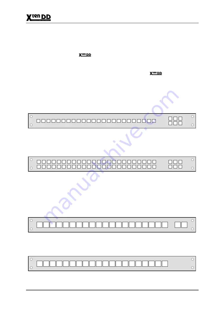
24-source selection button panel with 6 delegation buttons. Mechanical dimen-
sions: 19”, 1RU, small buttons.
The CP-300 and CP-330 control panel modules are basic single bus controllers.
24 inputs are provided with the CP-300 and 48 inputs are provided with the CP-330
panel. Delegation buttons provide access to 6 different busses.
THOMSON
CP-300 Control Panel
48-source selection button panel with 6 delegation buttons. Mechanical dimen-
sions: 19”, 1RU, small buttons.
THOMSON
CP-330 Control Panel
20-source selection button panel with 2 delegation buttons. Mechanical dimen-
sions: 19”, 1RU, large buttons.
The CP-3020 control panel module is a basic 20-input controller with two bus dele-
gation buttons. This panel can be expanded with the CP-3021 expansion panel mo-
dule to add access to 20 additional inputs. Up to 4 CP-3021 panels can be con-
nected to the main CP-3020 panel to extend access to 100 total inputs.
PHILIPS
CP-3020 Control Panel
20 source selection buttons for CP-3020 extension (19”, 1HE, large buttons)
PHILIPS
CP-3021 Control Panel
CP-300
CP-330
CP-3020
CP-3021
Summary of Contents for grass valley XtenDD
Page 17: ...Contents VI Planning and Installation Rev 0 04 2002 ...
Page 27: ...1 General 1 10 Planning and Installation Rev 0 04 2002 1 5 OVERALL BLOCK DIAGAM VIDEO ...
Page 29: ...1 General 1 12 Planning and Installation Rev 0 04 2002 ...
Page 33: ...2 Technical Data 2 4 Planning and Installation Rev 0 04 2002 ...
Page 39: ...3 Mounting Instructions 3 6 Planning and Installation Rev 0 04 2002 ...
Page 45: ...3 Mounting Instructions 3 12 Planning and Installation Rev 0 04 2002 ...
Page 61: ...3 Mounting Instructions 3 28 Planning and Installation Rev 0 04 2002 ...
Page 69: ...4 Connection and Startup 4 8 Planning and Installation Rev 0 04 2002 ...
Page 71: ...4 Connection and Startup 4 10 Planning and Installation Rev 0 04 2002 ...
Page 75: ...4 Connection and Startup 4 14 Planning and Installation Rev 0 04 2002 ...
Page 79: ...4 Connection and Startup 4 18 Planning and Installation Rev 0 04 2002 ...
Page 87: ...4 Connection and Startup 4 26 Planning and Installation Rev 0 04 2002 ...
Page 101: ...4 Connection and Startup 4 40 Planning and Installation Rev 0 04 2002 ...
Page 105: ...4 Connection and Startup 4 44 Planning and Installation Rev 0 04 2002 ...
Page 137: ...5 Initial Installation 5 32 Planning and Installation Rev 0 04 2002 ...
Page 138: ...5 Initial Installation 5 33 Planning and Installation Rev 0 04 2002 ...
Page 141: ...6 Installing System Accessories 6 3 Planning and Installation Rev 0 04 2002 ...
Page 162: ...6 Installing System Accessories 6 24 Planning and Installation Rev 0 04 2002 ...
Page 172: ...6 Installing System Accessories 6 34 Planning and Installation Rev 0 04 2002 ...
Page 196: ...7 Installing External Devices 7 24 Planning and Installation Rev 0 04 2002 ...
Page 214: ...7 Installing External Devices 7 42 Planning and Installation Rev 0 04 2002 ...
Page 218: ...7 Installing External Devices 7 46 Planning and Installation Rev 0 04 2002 ...
Page 226: ...7 Installing External Devices 7 54 Planning and Installation Rev 0 04 2002 ...
Page 244: ...7 Installing External Devices 7 72 Planning and Installation Rev 0 04 2002 ...
Page 250: ...7 Installing External Devices 7 78 Planning and Installation Rev 0 04 2002 ...


