


KAM-HD-MULTI—Instruction Manual
91
Kameleon HD Links and Web Pages
5.
This should place the recalled E-MEM file into the corresponding
E-MEM window.
6.
Select the corresponding
Recall
button to invoke this configuration.
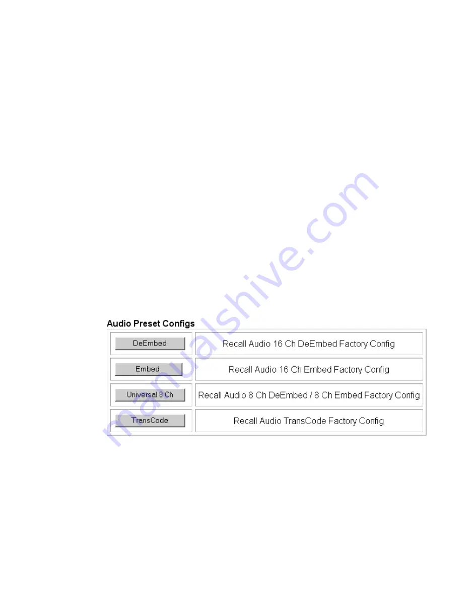
Audio Preset Configs
Four Audio Preset Configs buttons (
) are provided on the bottom
of the E-MEM web page for setting up audio I/O configuration for the rear
module and various audio parameters on the module. A preset configura-
tion can be selected depending on the particular audio application required
as described in
describes each preset configuration in detail and explains which configura-
tion is required for different audio applications
The following audio preset configurations are available:
•
DeEmbed
•
Embed
•
Universal 8 Ch
•
Transcode
Refer to
for a summary of each parameter set when the
Audio Preset Configurations are selected.
Figure 58. Audio Preset Config Buttons on E-MEM Web Page


