background image

SECTION 1 

COMMUNICATION INTERFACE MODULE 


PM055  Rev 2  00/08/31 

Thomson Technology 

13 


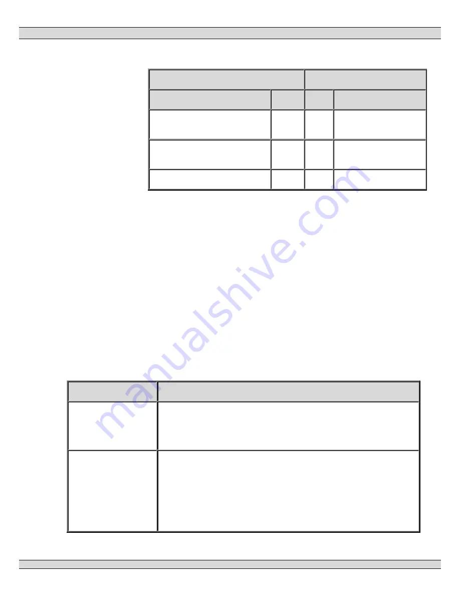
DB-25 from RS-485 converter


CIM Port 2


Signal 

Pin 

Pin 

Signal 

TXB+, RXB+ (jumpered) 

14,17 

1,4 

RXB+,TXB+ 
(jumpered) 

TXA-, RXA- (jumpered) 

2,5 

2,3 

RXA-, TXA- 
(jumpered) 

GND (optional) 

GND 


• 

Note that the RS-232 side of the RS-485 converter will most 

likely require the RTS line be connected along with TX, RX 

and GND. 

11. Troubleshooting 

Refer to the following list of typical problems. Consult the factory for any detailed 

information or for any problems not listed.  

CAUTION!!! Before opening the enclosure to perform any service task, it is 

imperative to isolate the control system from any possible source of power. 

Failure to do so may result in serious personal injury or death due to electrical 

shock.  

Service procedures must be undertaken by qualified personnel only!  


SYMPTOM


CORRECTIVE ACTION


CIM does not 
power up even 
with correct DC 
power applied 

Check that there are no wiring errors/short circuits connected to 
the CIM. Note: The CIM Module contains an electronic fuse that 
triggers upon an overload or overvoltage condition and does not 
reset until the supply voltage is removed.  

Failure to 
communicate with 
PC (direct 
connected). 

Verify all communication cables are connected to the correct 
ports.  

Ensure that the RTU's (TSC 800 and MEC 20) are connected to 
Port 3 on the CIM.  

Ensure the correct MEC 20 communication port (J7) is utilized. 
Port J7 is white in color. The black RJ45 connector on the MEC 

Summary of Contents for CIM 3.0

Page 1: ...Canada V1M 3B1 Telephone 604 888 0110 Telefax 604 888 3381 E Mail info thomsontechnology com www thomsontechnology com REMOTE COMMUNICATION SYSTEM VERSION 3 0 USER MANUAL Copyright 1999 by Thomson Te...

Page 2: ......

Page 3: ...6 PORT 3A B 7 7 CIM OPERATION FUNCTIONS 7 8 CIM BLOCK DIAGRAM 8 9 CIM SPECIFICATIONS 8 10 CIM INSTALLATION 9 10 1 BATTERY SUPPLY INPUT 9 10 2 REMOTE COMMUNICATION WIRING 10 10 3 DIELECTRIC TESTING 10...

Page 4: ...6 IDENTIFY CONTROLLERS 21 2 7 STEP 7 VIEW CONTROLLER DATA 21 2 8 STEP 8 ISSUE CONTROLLER COMMANDS 21 2 9 STEP 9 SAVE RESTORE SITE LIST INFORMATION 22 3 CONFIGURATION 22 3 1 PASSWORDS 22 3 2 SITE LIST...

Page 5: ...AMPLE REMOTE KEY PRESS OPERATION 51 5 READ HOLDING REGISTERS TYPE 3 52 5 1 READ HOLDING REGISTERS REQUEST 52 5 2 READ HOLDING REGISTERS RESPONSE 52 5 3 EXAMPLE READ REGISTERS 200 TO 201 52 6 APPLICATI...

Page 6: ...SUMMARY 63 16 5 MEC 20 ANALOG VALUES 64 16 6 MEC 20 DISPLAY DETAILS 66 16 7 MEC 20 FAULT DETAILS 66 17 TSC 800 REGISTER TABLES 67 18 TSC 800 MESSAGES VERSION 1 0 67 18 1 TSC 800 PRESS KEY 68 18 2 TSC...

Page 7: ...Module CIM The CIM provides the hardware and software interface between a Modbus compliant device customer supplied and the specific microprocessor based controllers as used at a generator site Remote...

Page 8: ...bus option that is intended for direct PLC function where remote access is not necessary With onboard modem support CIM 3 0 offers remote telephone connectivity with auto callout and pager support wit...

Page 9: ...when an RTU fault occurs frees the user from continual monitoring It also allows for immediate remote response to problems 3 Hardware Interface The main features of the CIM are described as follows w...

Page 10: ...ly voltage must be removed for 30 seconds then re applied 3 4 Internal Modem The CIM is provided with an internal 14 4 Kbaud modem The modem is internally connected between the telephone port and port...

Page 11: ...nection to TTI MEC 20 and or TSC 800 controllers Port 3B is internally wired in parallel with Port 3A 3 8 Port 3A This port may be interconnected to a remote terminal unit RTU or directly to a PC Port...

Page 12: ...Connection 2 TIP Input output 3 Ring Input output 4 No Connection No Connection 5 No Connection No Connection 6 5 Port 2A B Detail pin numbers and usage designations for Port number 2A B are as follo...

Page 13: ...M provides the necessary hardware interface i e COM Ports as well as the Modbus software protocol interface Protocol Data Processing The CIM receives incoming communication signals from various types...

Page 14: ...ne Line G R D PRODUCTS ICS DESIGN CIM 1029012 VSD Rev 0 99 08 26 Modbus TM Compliant Device 9 CIM Specifications Power supply 8 to 35Vdc negative ground Power consumption 5 watts max Operating tempera...

Page 15: ...rectly from the battery terminals to the control panel where the CIM module is located to avoid voltage drop in the starter cables and starter motor commutation noise CAUTION The battery charger must...

Page 16: ...ctric testing on the CIM connected in the circuit as serious damage will occur to the module 10 4 Mounting Location Installation The CIM Module is designed for mounting directly onto a control panel i...

Page 17: ...etwork 10 6 1 Host PC Connection The host PC connection to the CIM requires a null modem adapter as both devices believe they are DTE 10 6 1 1 Host PC DB 25 To CIM DB 9 DTE DB 25 DB 9 CIM GND 1 n c GN...

Page 18: ...port 2 see below wiring Insure that the correct handshaking signals are connected on the RS 232 side of the RS 485 422 converter Many RS 485 converters use the RTS line to control the transmitter whi...

Page 19: ...ol system from any possible source of power Failure to do so may result in serious personal injury or death due to electrical shock Service procedures must be undertaken by qualified personnel only SY...

Page 20: ...cted Verify PC modem operates correctly test independently with another software system Verify PC modem is set for 9600 baud operation Ensure phone numbers programmed for both PC site location and RTU...

Page 21: ...the CIM is being addressed with the correct node address The factory default CIM node address is 1 this should not be confused with the RTU node addresses connected to Port 3 of the CIM 11 1 Database...

Page 22: ...internal modem of the CIM on Port 1 The host PC modem must already be configured before attempting a remote connection See the operating system help for installing and configuring modems Version 3 1...

Page 23: ...ort 2 auto detect feature for the hardware protocol see CIM Port 2 bounded controller addresses for faster detection see CIM Advanced CIM Port 2 can now be configured for speeds from 1200bps up to 19...

Page 24: ...sists of two files the THS3v0 EXE file and the THS3v0 CHM file Both files should be copied to a directory on your hard drive such as C THS The first file THS3v0 EXE is the THS 2000 executable You can...

Page 25: ...or toolbar button or press F9 This command will normally bring up a list of accessible sites however if no sites are defined you will be required to choose a host connection method This dialog box is...

Page 26: ...g the remote site The description field is optional and can be used to describe the site The phone number is entered for a remote site The name and password parameters must match the CIM on the intend...

Page 27: ...l At this point you are connected and communicating with the CIM and its controllers The status bar at the bottom of the window will flicker and display a message similar to Connected to EastWing 2 7...

Page 28: ...rameters is generally done once and then used many times in an operational capacity 3 1 Passwords The THS 2000 program can be secured with the use of passwords The password levels are 3 1 1 READ ONLY...

Page 29: ...to answer allowing any of the listed remote sites to call THS 2000 in case of an alarm condition The list of sites the site properties the connection method and the auto answer settings are all stored...

Page 30: ...n be opened but they will only contain a single site in the site list If this file is modified and saved you will no longer be able to open it from previous versions of THS 2000 3 2 3 Saving A Site li...

Page 31: ...nd password of the new site which is the name and password of the CIM on that site The description can be any descriptive text The phone number can only be entered for a host connection that is a mode...

Page 32: ...on the name of the site in the site list dialog 3 3 4 Host Connection The host connection method can be changed from the Connect Using command of the Site menu or the Connect Using button of the Conn...

Page 33: ...modified Supported baudrates are 1200 2400 4800 9600 14400 and 19200 The Restore Defaults button set the parameters to RS 232 signal type no parity 8 data bits 1 stop bit and 9600 baud The RTS activat...

Page 34: ...nfiguration and callout phone numbers When a value is modified the Apply button will become click able Clicking the Apply button will send the changes to the CIM also clicking the OK button will send...

Page 35: ...M3 0 are limited to 12 characters for the site name and 8 characters for the password Note all CIMs that are intended for callout operation to the same site list must have unique site names 3 4 2 CIM...

Page 36: ...se fields appears as N A when communicating with one of these older devices 3 4 3 CIM Callout The CIM Callout tab configured the callout feature which allows the CIM to call the host in case of an ala...

Page 37: ...ttempts this is reflected in this dialog box by tying all there attempts choices together so if one is changed they are all changed 3 4 4 CIM Database All the properties of the CIM described in this c...

Page 38: ...ked unless you know what you are doing or you are under the guidance of a qualified service person 3 4 5 CIM Port 2 A CIM connected directly to a PC host or a Programmable Logic Controller PLC is conn...

Page 39: ...ity 8 data bits 1 stop bit 9600 baud and 20 millisecond receive timeout The Fixed Modbus Mode option is for enabling the fixed Modbus mode for operation with a Programmable Logic Controller PLC Once i...

Page 40: ...read only you may not change any of these values they are fixed 3 4 7 CIM Advanced The CIM Advanced tab of the Current Site Properties dialog box allows you to change some of the more advanced feature...

Page 41: ...When THS 2000 is communicating with an older CIM the CIM Advanced dialog box is not available 3 5 Controller Configuration This section deals with the adding and removing of controllers The controlle...

Page 42: ...Removing A Controller Removing a controller is accomplished by selecting the Remove item from the Controller menu which brings up the Remove Controller dialog box as shown below The controller to be...

Page 43: ...one for the TSC 800 The MEC 20 properties dialog box is shown in the following figure From this window the description can be modified and other properties such as the controller address and the faul...

Page 44: ...configured from the Auto answer Settings command of the Site menu as shown below When the auto answer feature is enabled the THS 2000 software will accept calls from any site in the currently loaded s...

Page 45: ...three different levels of security depending on the password you entered The levels are read only read write and master see Passwords for more information You also have the option of selecting Demo m...

Page 46: ...to press in combination with the ALT key Many of the important commands are available using function keys these are indicated in the pull down menus 4 1 5 Toolbar The toolbar provides instant access t...

Page 47: ...eference 4 1 10 Exiting The Exit command from the File menu will exit THS 2000 disconnecting any outstanding connections 4 2 Connecting Sites A site is made up of a single CIM connected to one or more...

Page 48: ...MEC 20 Microprocessor Engine Controller and the TSC 800 Transfer Switch Controller The main view of the THS 2000 provides a simulated front panel of a single controller Controllers can be added remov...

Page 49: ...ow shows the view of a TSC 800 connected to a remote CIM Just as the MEC 20 the black part of the view is a direct emulation of the TSC 800 front panel The faults and values are displayed and updated...

Page 50: ...menu or the toolbar button while viewing a controller will print the currently displayed values in a simple text format The print command will print the list of controllers when invoked while viewing...

Page 51: ...controllers and determine the cause of the alarm The status bar will also display a countdown of the remaining connection time in seconds 5 CIM Bypass Wiring The CIM bypass connection mode of operatio...

Page 52: ...232 NULL connection between the modem and the converter must pass all handshake signals as shown in the following diagram TD RD RTS CTS DSR CD DTR GND TD RD RTS CTS DSR CD DTR GND 3 2 7 8 6 1 4 5 3 2...

Page 53: ...1 AT W0 6 Troubleshooting SYMPTOM CORRECTIVE ACTION Cannot communicate with the site See the CIM User Manual Troubleshooting for possible solutions THS 2000 software locks up The Host software may lo...

Page 54: ...This instruction manual provides detailed information on the CIM 3 0 Modbus protocol For detailed information on a the CIM 3 0 hardware and installation see the Section 1 For information on operation...

Page 55: ...n most significant byte first format Any unused fields contain zeroes When describing the fields FALSE equals zero and TRUE equals non zero At the Datalink Layer the host master is responsible for pol...

Page 56: ...values show the necessary pre transmit delays to insure reliable transmission of data to the CIM baudrate delay ms 1200 130 2400 80 4800 40 9600 30 14400 30 19200 30 The typical CIM MEC 20 and TSC 80...

Page 57: ...is shown below ss 10 aaaa pppp cccc ss MEC 20 ID 00 to FF aaaa Starting register 4aaaa same number as the write packet pppp Register count same number as the write packet cccc CRC 16 see CRC Calculati...

Page 58: ...holding register request is used for read data from the controller Numeric values are shown in hexidecimal 5 1 Read Holding Registers Request Field addressing is done with the following format ss 03 a...

Page 59: ...eant for a CIM or MEC 20 The data block protocol from the MEC 20 will be described in the next section The CIM port configuration table is used to change the port type RS 232 485 422 and data protocol...

Page 60: ...r allowable values can be further limited uint16 1 0 65535 unsigned 16 bit integer allowable values can be further limited string n special character 0 255 string ordered MSB1 LSB1 MSB2 LSB2 struct n...

Page 61: ...in multiple CIM configurations The CIM s are slaves to any device connected to Port 2 However the CIM acts like a Master to anything connected to Port 3 Communication to the individual MEC 20 s will...

Page 62: ...s hex Register Count Data Format Value Requested Link protocol 40385 180 1 enum 0 THS 1 Modbus 2 Fixed Modbus Requested Line protocol 40386 181 1 enum 0 logoff 1 RS 232 2 RS 422 3 RS 485 4 Modem Login...

Page 63: ...ersion lower 40430 1AD 1 uint16 0 to 65535 Modbus protocol version upper 40431 1AE 1 uint16 0 to 65535 Modbus protocol version lower 40432 1AF 1 uint16 0 to 65535 13 CIM RTU List Field Register decima...

Page 64: ...below The slave address and type are encoded in the following 2 byte structure byte0 slave type 0 none 1 MEC 20 2 TSC 800 byte1 slave address 0 to 255 14 CIM Callout Field Register decimal Address hex...

Page 65: ...Valid Data Display 40514 201 1 struct see MEC 20 Valid Data Display MEC 20 Version 40515 40527 202 204 3 struct see MEC 20 Get Version MEC 20 Summary 40518 40523 205 20A 6 struct see MEC 20 Get Summa...

Page 66: ...Digital Fault 9 Message 40622 40629 26D 274 8 string length 16 bytes see MEC 20 Fault Details MEC 20 Digital Fault 10 Message 40630 40637 275 27C 8 string length 16 bytes see MEC 20 Fault Details MEC...

Page 67: ...ils MEC 20 Low Temp 40865 40872 360 367 8 string length 16 bytes see MEC 20 Fault Details MEC 20 Hi Temp1 message 40873 40880 368 36F 8 string length 16 bytes see MEC 20 Fault Details MEC 20 Hi Temp2...

Page 68: ...field contains the number of times the key is to be pressed The response message contains the current display contents 16 2 MEC 20 Valid Data Display The Data Display Valid byte is used to determine...

Page 69: ...Shutdown LED Bit 13 contains TRUE if an alarm is active This bit is the equivalent of the Alarm LED Bit 12 contains TRUE if the speed signal is present This bit is the equivalent of the Speed Signal P...

Page 70: ...18 is digital fault 2 Fault name is programmable Bit 17 is digital fault 1 Fault name is programmable Bit 16 is low oil pressure 2 Bit 15 is low oil pressure 1 Bit 14 is high engine temperature 2 Bit...

Page 71: ...age in volts 1 Phase mode This field contains the phase AB voltage in volts byte2 byte3 3 phase mode This field contains the phase BC voltage in volts 1 Phase mode This field contains the phase AN vol...

Page 72: ...n byte0 to byte15 This field contains the ASCII characters from the LCD top line Group 1 Field Description byte0 to byte15 This field contains the ASCII characters from the LCD bottom line 16 7 MEC 20...

Page 73: ...o 41065 Field Register decimal Address hex Register Count Data Format Value TSC 800 Key Press write only reg 41025 400 1 uint16 see TSC 800 Press Key TSC 800 Valid Data Display 41026 401 1 uint8 see T...

Page 74: ...used byte1 This field contains the number of times the key is to be pressed The response message contains the current display contents 18 2 TSC 800 Valid Data Display The Data Display Valid byte byte1...

Page 75: ...nused in standard mode This bit contains TRUE if the Src1 Start output is enabled in dual prime mode Bit 10 contains TRUE if the Src2 Start output is enabled Bit 9 contains TRUE if the Src1 Pretransfe...

Page 76: ...normal Src2 auto 33 Src1 normal Src2 failed 34 Src1 normal Src2 normal 35 Src1 normal Src2 offload test 36 Src1 normal Src2 onload test 37 Src1 normal Src2 ready 38 Src1 normal Src2 running 39 Src1 n...

Page 77: ...81 Src1 starting Src2 onload test 82 Src1 starting Src2 ready 83 Src1 starting Src2 running 84 Src1 starting Src2 starting 85 Src1 starting Src2 switch off 86 Src1 switch off Src2 auto 87 Src1 switch...

Page 78: ...ntains the hour of the system time Valid values are 0 59 byte12 This field contains the minute of the system time Valid values are 0 59 byte13 This field contains the second of the system time Valid v...

Page 79: ...hase AB voltage in volts byte20 byte21 This field is unused byte22 byte23 This field is unused byte24 byte25 This field contains the load frequency in tenths of hertz 18 6 TSC 800 Display Details The...

Page 80: ...iled information using the terminology of that paper the CRC algorithm used by the CIM is Name CRC 16 Width 16 Poly 8005 Init FFFF RefIn True RefOut True XorOut 0000 Check BB3D The following is a C co...

Page 81: ...SECTION 3 CIM PROTOCOL PM055 Rev 2 00 08 31 Thomson Technology 75 20 NOTES...

Reviews: