-7-
Electrical Requirements
The unit construction provides protection against the risk of electric
shock by grounding appropriate metal parts . The protection may not
function unless the power cord is connected to a properly grounded
outlet. It is the user's responsibility to assure a proper ground connec-
tion is provided.
Refer to the serial number label on the rear of the unit to identify the specific
electrical requirements of your unit.
Make sure the voltage of the power source meets the specified voltage, ±10%.
Voltage Selection
If the unit is to be operated from a 220 to 240 volt source, a voltage selector
inside the unit must be reset. See Section VII, Service for instructions on
changing the voltage selection.
Plumbing
Requirements
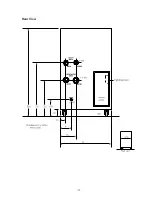
The plumbing connections are located on the rear of the unit and are la-
belled FACILITY WATER and RECIRCULATING WATER. FACILITY
WATER connections are 1 inch nominal FPT. RECIRCULATING WATER
connections are 1½ inch nominal FPT. See illustration on page 19.
Before installing the unit to an instrument that previously used tap water as a
cooling fluid, flush the instrument several times to remove any rust or scale
that has built up. The manufacturer of the instrument should be able to
recommend a cleaning fluid for their equipment.
Connect the FACILITY WATER SUPPLY to the cooling water source.
Connect the FACILITY WATER RETURN to the drain.
Connect the RECIRCULATING WATER SUPPLY to the inlet of the instru-
ment being cooled. Connect the RECIRCULATING WATER RETURN to the
outlet of the instrument being cooled.
Flexible tubing, if used, should be of heavy wall or reinforced construction.
All tubing should be rate to withstand 80 psi at +40°C. Make sure all tubing
connections are securely clamped. Avoid running tubing near radiators, hot
water pipes, etc. If substantial lengths of tubing are necessary, insulation
may be required to prevent loss of cooling capacity.
Tubing and insulation are available from Thermo. Contact our Sales Department
for more information (see Preface, After-sale Support).
Summary of Contents for NESLAB System IV
Page 19: ... 18 Section VII Diagrams Flow Diagram ...
Page 20: ... 19 Rear View ...


