


-6-
Section III Installation
Site
The unit should be placed in a laboratory or clean industrial environment with
easy access to a facility cooling water and a drain.
Facility Water
Requirements
Limit the facility water inlet pressure to less than 150 psi (10,2 Bar) and
limit the facility water inlet pressure to outlet pressure differential
across the System IV to less than 35 psid (2,4 Bar).
Refer to the Cooling Capacity chart in Section II, Specifications. The flow rate
of the cooling water supply must meet or exceed these requirements for the
unit to operate at its full rated capacity. If the cooling water does meet these
standards, the cooling capacity will be derated. The chart is based on a 10°C
difference between the temperature of the cooling water supply and the pro-
cess fluid entering the instrument being cooled.
As the heat load increases, the required flow rate of the cooling water supply
increases. For example, if the heat load is 60 kilowatts, only 20 gallons per
minute is required to remove the heat. However, if the heat load is 80
kilowatts, 26 gallons per minute is required.
The flow meter on the front of the unit does not measure the flow rate of the
cooling water supply. The flow meter measures the flow rate of the cooling
fluid returning to the instrument being cooled.
The approximate facility side water pressure drop though the unit is shown
on the graph below.
5
10
15
20
25
30
35
10
8
6
4
2
Pressure
Drop
(PSI)
Flow Rate (GPM)
Summary of Contents for NESLAB System IV
Page 19: ... 18 Section VII Diagrams Flow Diagram ...
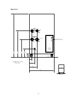
Page 20: ... 19 Rear View ...


