


Engine Maintenance (Rev. 12/03)
47
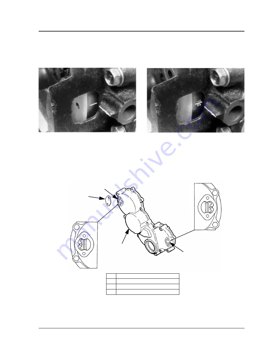
TC Mark on Flywheel
2.
Before installing the pump, rotate the gear until the “O”
marked on the gear is approximately in the 10 o’clock
position as you face the gear end of the pump.
3.
Remove the injection pump access cover from the tim-
ing gear cover.
ditdc
Injection Timing Mark
NOTE: The injection timing mark is a line scribed in
the flywheel approximately 35 mm (1-3/8 in.) from the
TC mark. The injection timing mark has no identifi-
cation markings.
The engine now has the No. 1 cylinder at the fuel injec-
tion mark of its compression stroke.
diitm
1.
Injection Pump Access Hole
2.
Access Cover
3.
Timing Gear Cover
4.
Cam Gear Access Hole
aea846
2
1
3
4
Summary of Contents for SB-190 30
Page 4: ......
Page 8: ......
Page 14: ...4...
Page 26: ...Unit Description Rev 12 03 16 Front View AJA890...
Page 40: ...Operating Instructions Rev 12 03 30...
Page 74: ...64...
Page 92: ...82...
Page 100: ...90...
Page 113: ...103 SB 100 190 Schematic Diagram Page 1 of 2...
Page 114: ...104 SB 100 190 Schematic Diagram Page 2 of 2...
Page 115: ...105 SB 100 190 Wiring Diagram Page 1 of 5...
Page 116: ...106 SB 100 190 Wiring Diagram Page 2 of 5...
Page 117: ...107 SB 100 190 Wiring Diagram Page 3 of 5...


