


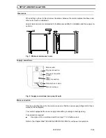


Levelling the shelves
The shelves can be aligned with the aid of a spirit level with height-adjustable feet.
Functional principle
The atmosphere in the chamber can be regulated in relation to its temperature, CO
2
concentra-
tion, O
2
concentration (optional) and relative humidity.
Heating system
The temperature inside the unit can be regulated in the range of +7°C to +50°C, but must be at
least +5°C (approx. +7°C for the O
2
version) above the ambient temperature of the unit.
Condensation on the glass door is largely prevented by heating the unit door. If the unit door is left
open for a long period of time, however, condensation cannot be ruled out.
The unit door heater can be switched off as required (refer to Chapter headed OPERATION).
This enables the unit to be operated at high ambient temperatures or when the operating tem-
perature is only supposed to exceed the ambient temperature by approx. +4°C.
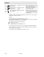
Example:
Ambient temperature
Operating temp.
Heating of unit door
+25°C
+37°C
ON
+24°C
+28°C
OFF
+32°C to +33°C
+37°C
OFF
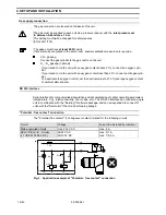
Gassing
Connection to the gas supplies (CO
2,
, O
2
or rather N
2
) are located on the rear panel of the incuba-
tor.
The CO
2
content of the atmosphere in the chamber can be regulated in the range 0% to
20%.
The O
2
concentration inside the unit can be regulated in the range 3% to 90% O
2
by admit-
ting N
2
(< 21% O
2
) or O
2
(> 21% O
2
).
The sum of the nominal values for CO
2
+ O
2
must not exceed 90%.
Example: 10% CO
2
+ 80% O
2
= 90% (possible)
20% CO
2
+ 80% O
2
= 100% (impossible)
Before entering the chamber, all gases pass through a filter where particles larger than 0.3 µm
are retained. Filter efficiency is 99.998%.
A fan integrated in the rear of the interior wall ensures that the gases and the incubator atmos-
phere are thoroughly mixed.
The sensors for CO
2
, O
2
(option) and relative humidity are also located on the rear panel of the in-
terior wall. These sensors measure the parameters inside the unit and transmit corresponding sig-
nals to the closed-loop controller.
A pressure compensation vent on the rear panel of unit avoids undesirable pressure build-up in-
side the unit during the admission of gases.
The place of installation must be thoroughly ventilated in order to expel the gases escaping
around pressure compensation vent.
5. DESCRIPTION OF THE UNIT
50 079 041
13/45


