


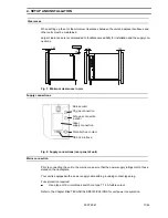


Gas supply connection
The gas connection are located on the back of the unit.
The gas must be supplied to each unit via a pressure reducer with the inlet pressure set
to between 0.8 and max. 1 bar.
This setting must not be changed for safety reasons
(FRG: ZH 1/119).
The gases must have at least 99.5% purity.
If several units are placed in the same room, special ventilation measures are required.
CO
2
gassing
Connect the gas cylinder to the gas nozzle on the unit.
O
2
/ N
2
gassing (optional)
If you intend to run the unit with an oxygen content above 21%, connect an oxygen cylin-
der.
If you intend to run the unit with an oxygen content less than 21%, connect a nitrogen cylin-
der.
To deactivate the oxygen control, set the nominal value to 21.0% (average oxygen content
of ambient atmosphere).
RS 232 interface
Serial interface for computer-aided acquisition and documentation of critical operating parameters
(temperature, CO
2
, relative humidity, error codes, etc.). The RS 232 interface can connect a single
unit in combination with the "Kelvilog"
software package, and can be expanded to connect 31
units with the "Netcontrol"
hard- and software package.
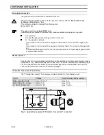
"Potential - free contact" connection
The "Potential-free contact" (1 changeover contact) is rated for the following circuits:
Circuit
Voltage
Fuse to be installed by customer
Mains-operated circuits
max. 250 V AC
max. 6 A
SELV / SELV - E - circuits
(cf. VDE 0100 Part 410)
25/50 V AC
60/120 V DC
max. 2/1 A
max. 1/0.5 A
Fig. 3 : Application example of "Potential - free contact" connection
3
1
2
X
View X
PE
3
1
2
L
F1x
T2A
H1x
Kx
S1x
Kx
H2x
Kx
A1
A2
N
1s
4. SETUP AND INSTALLATION
12/43
50 079 041


