


59
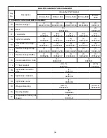
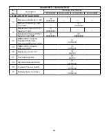
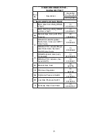
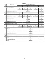
BOILER COMBUSTION CHAMBER
Key
No.
Description
(Quantity) Part Number
EVCA-750
EVCA-1000
EVCA-1500 EVCA-2000
EVCA-
3000
1. COMBUSTION CHAMBER ASSEMBLY
1A
Heat Exchanger
(1)
603EVC07510
(1)
603EVC01000
(1)
603EVC01500
(1)
6035630061
(1)
104057-01
1B
Base
(1)
61556024
(1)
103078-01
1F
Tube Baffle
(31)
70356215
(31)
70356216
(31)
70356217
(31)
70356218
(41)
70356317
1G Sight Tube Baffle
(1)
70356223
(1)
70356224
(1)
70356225
(1)
70356226
(1)
70356320
1H
Combustion Pan Sup-
port
(4)
603562041
(4)
603562051
(4)
603562061
(4)
603562071
(6)
60356210
1I
Heat Exchanger Wrap-
per
(1)
804EVC2003
(1)
804EVC2004
(1)
804EVC2005
(1)
804EVC2006
(1)
103081-02
1J
Heat Exchanger Baffle
(1)
70356236
(1)
70356237
(1)
70356238
(1)
70356239
(1)
70356242
1K
Condensate Drain Tube
(1)
806EVC01
(1)
8065601
1L
1” Fiber Gasket
(14 LF)
9206032
(19.5)
9206032
1M Sight Glass Lens Re-
tainer
(1)
7186019
1N
Sight Glass Gaskets
(2)
8206039
1Q Sight Glass Lens
(1)
8026082
1R
Wrapper Banding
(24 LF)
92466028
(25.5 LF)
92466028
1S
Banding Buckle
(4)
80860946
1T
Temperature Probe (not
shown)
(2)
101935-01
Summary of Contents for EVCA SERIES
Page 14: ...14 Figure 4 Typical Vertical Pressurized Venting ...
Page 16: ...16 Figure 6 Vertical Air Intake Piping Figure 5 Horizontal Air Intake Piping ...
Page 19: ...19 Figure 8 Schematic Boiler Piping ...
Page 25: ...25 Figure 9a 208 230 480V 1PH 3PH 60HZ Supply Power Wiring Schematic ...
Page 26: ...26 Figure 9b 120V 1PH 60HZ Supply Power Wiring Schematic ...
Page 27: ...27 Figure 9c Control Wiring Schematic EVCA 750 2000 ...
Page 29: ...29 Figure 9e Control Wiring Schematic EVCA 3000 ...
Page 32: ...32 Figure 10 Modular System Horizontal Air Intake Piping ...
Page 33: ...33 Figure 11 Modular System Vertical Air Intake Piping ...
Page 34: ...34 Figure 12 Modular System Typical One Pipe Water Piping ...
Page 35: ...35 Figure 13 Modular System Typical Primary Secondary Water Piping ...
Page 36: ...36 Figure 14 Modular System Typical Primary Secondary without System Pump ...
Page 37: ...37 Figure 15 Modular System Typical Reverse Return Water Piping ...
Page 38: ...38 Figure 16 Modular System Reverse Return with System Pump Only ...
Page 39: ...39 Figure 17 Modular System Typical Primary Secondary with Reverse Return ...
Page 55: ...55 Figure 18 Cleaning Secondary Heat Exchanger 1 2 ...
Page 56: ...56 This page intentionally left blank ...
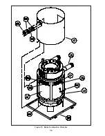
Page 58: ...58 Figure 19 Boiler Combustion Chamber ...
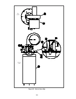
Page 60: ...60 Figure 20 Burner Assembly FRONT VIEW TOP VIEW ...
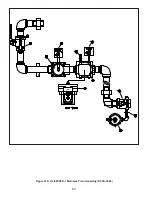
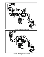
Page 62: ...62 Figure 21a UL FM CSD 1 Main Gas Train Assembly EVCA 750 2000 ...
Page 64: ...64 Figure 21b UL FM CSD 1 Main Gas Train Assembly EVCA 3000 ...
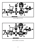
Page 66: ...66 Figure 22a DB B Gas Train 750 Figure 22b DB B Gas Train 1000 2000 ...
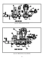
Page 68: ...68 Figure 22c DB B w POC Gas Train 750 Figure 22d DB B w POC Gas Train 1000 2000 ...
Page 70: ...70 Figure 22e DB B Gas Train EVCA 3000 Figure 22f DB B w POC Gas Train EVCA 3000 ...
Page 72: ...72 Figure 23 Jacket ...
Page 74: ...74 Figure 24 EVCA 750 1000 and 1500 Secondary Heat Exchanger and Housing ...
Page 78: ...78 Figure 25b EVCA 3000 Secondary Heat Exchanger and Housing ...
Page 80: ...80 Figure 26 Control Panel Assembly ...
Page 82: ...82 Figure 27 Bishop Pilot Assembly ...
Page 97: ...97 NOTES ...
Page 98: ...98 NOTES ...
Page 99: ...99 NOTES ...


