


50
B.
TROUBLESHOOTING GUIDE
Alarm Messages
Alarm Messages are shown one at a time in priority order. The message closest to the top of this list is displayed first.
Following messages are not shown until the higher priority message has cleared. All alarm messages are also stored
in the Fault History.
LCD Display
Alarm Message
Recommended
Action
Explanation
Low Water Level
Manually Reset the Low
Water Cutoff
Low Water Cutoff Switch
When this option is configured and an instrument is installed, the manual reset
low water safety relay is preventing the boiler from starting. If terminal (LC) does
not receive power and the Call For Heat output (CH) is powered, the “Low Water
Level” Message is displayed.
Off Switch
Turn Burner Switch On
Burner Switch is Off
Control switch is in the OFF position and is preventing the boiler from starting. If
terminal (OO) does not receive power and the Call For Heat output (CH) is pow-
ered the “OFF Switch” Message is displayed.
Low Water Flow
Ensure Boiler Pump is
Running and Boiler
Water Flow is
Unobstructed
Low Water Flow Switch
Low water flow is preventing the boiler from starting. If terminal (WF) does not
receive power and the Call For Heat output (CH) is powered, the “Low Water
Flow” Message is displayed.
Fuel Limit
Manually Reset the Fuel
Pressure Switch
Low or High Gas Pressure Switch
The low or high gas pressure switch is preventing the boiler from starting. If
terminal (GP) does not receive power and the Call For Heat output (CH) is
powered, the “Fuel Limit” Message is displayed.
High Temp Limit
Manually Reset the
High Temperature
Aquastat
High Limit Temperature
The high temperature limit (HL) (and operational temperature limit when
provided) aquastat is preventing a boiler start. If terminal (HL) does not receive
power and the Call For Heat output (CH) is powered, the “High Temp Limit”
Message is displayed.
Low Air Flow
Check Combustion Air
Blower and Air
Pressure Switch
Settings and Wiring
Low Air Flow or Blocked Vent Switch Not Made
The air flow (and blocked vent switch when installed) is preventing a boiler start.
If terminal (CA) does not receive power and the Call For Heat output (CH) is
powered, the “Low Air Flow” Message is displayed.
FSG Fault
Manually Reset
Required, Refer to
Flame Safeguard
Manual
Corrective Actions
Flame Safeguard Fault
The Flame Safeguard is preventing a boiler start. If terminal (AL) receives power
at any time, the “Flame Failure” Message is displayed.
Outlet Temp Fail
Check Wiring and
Sensor
Boiler Outlet Temperature Sensor Fail
The boiler outlet temperature sensor is not connected or is reading above or
below a valid range. When the boiler outlet sensor fails and the Outlet Sensor
mode was selected, the control will transfer to Lost Sensor Blind Mode.
Inlet Temp Fail
Check Wiring and
Sensor
Boiler Inlet Temperature Sensor Fail
The boiler inlet temperature sensor is not connected or is reading above or below
a valid range. When the boiler inlet sensor fails, the mixing valve output will drive
to 0% and low temperature alarm and maximum water differential (boiler outlet
minus boiler inlet) temperature hold are disabled.
OA Temp Fail
Check Wiring and
Sensor
Outside Air Temperature Sensor Fail
The outside air sensor is configured and is not connected or is reading above or
below a valid range. When the outside air sensor fails, the warm weather shut-
down (WWSD) and outside air reset control logics are disabled.
Remote Temp Fail
Check Wiring and
Sensor
Remote System Temperature Sensor Fail
The remote system temperature sensor is configured and is not connected or is
reading above or below a valid range. If Remote System Temperature Sensor
mode was selected, the control will transfer to Boiler Outlet Sensor Mode.
Summary of Contents for EVCA SERIES
Page 14: ...14 Figure 4 Typical Vertical Pressurized Venting ...
Page 16: ...16 Figure 6 Vertical Air Intake Piping Figure 5 Horizontal Air Intake Piping ...
Page 19: ...19 Figure 8 Schematic Boiler Piping ...
Page 25: ...25 Figure 9a 208 230 480V 1PH 3PH 60HZ Supply Power Wiring Schematic ...
Page 26: ...26 Figure 9b 120V 1PH 60HZ Supply Power Wiring Schematic ...
Page 27: ...27 Figure 9c Control Wiring Schematic EVCA 750 2000 ...
Page 29: ...29 Figure 9e Control Wiring Schematic EVCA 3000 ...
Page 32: ...32 Figure 10 Modular System Horizontal Air Intake Piping ...
Page 33: ...33 Figure 11 Modular System Vertical Air Intake Piping ...
Page 34: ...34 Figure 12 Modular System Typical One Pipe Water Piping ...
Page 35: ...35 Figure 13 Modular System Typical Primary Secondary Water Piping ...
Page 36: ...36 Figure 14 Modular System Typical Primary Secondary without System Pump ...
Page 37: ...37 Figure 15 Modular System Typical Reverse Return Water Piping ...
Page 38: ...38 Figure 16 Modular System Reverse Return with System Pump Only ...
Page 39: ...39 Figure 17 Modular System Typical Primary Secondary with Reverse Return ...
Page 55: ...55 Figure 18 Cleaning Secondary Heat Exchanger 1 2 ...
Page 56: ...56 This page intentionally left blank ...
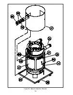
Page 58: ...58 Figure 19 Boiler Combustion Chamber ...
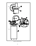
Page 60: ...60 Figure 20 Burner Assembly FRONT VIEW TOP VIEW ...
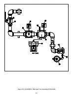
Page 62: ...62 Figure 21a UL FM CSD 1 Main Gas Train Assembly EVCA 750 2000 ...
Page 64: ...64 Figure 21b UL FM CSD 1 Main Gas Train Assembly EVCA 3000 ...
Page 66: ...66 Figure 22a DB B Gas Train 750 Figure 22b DB B Gas Train 1000 2000 ...
Page 68: ...68 Figure 22c DB B w POC Gas Train 750 Figure 22d DB B w POC Gas Train 1000 2000 ...
Page 70: ...70 Figure 22e DB B Gas Train EVCA 3000 Figure 22f DB B w POC Gas Train EVCA 3000 ...
Page 72: ...72 Figure 23 Jacket ...
Page 74: ...74 Figure 24 EVCA 750 1000 and 1500 Secondary Heat Exchanger and Housing ...
Page 78: ...78 Figure 25b EVCA 3000 Secondary Heat Exchanger and Housing ...
Page 80: ...80 Figure 26 Control Panel Assembly ...
Page 82: ...82 Figure 27 Bishop Pilot Assembly ...
Page 97: ...97 NOTES ...
Page 98: ...98 NOTES ...
Page 99: ...99 NOTES ...


