


OPERATION
4-2
Manual 0-2782
5. TEMP Indicator
Normally OFF. Yellow indicator turns ON when the
internal temperature senors detect temperatures
above normal limits. The unit should be allowed to
cool before continuing operation.
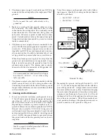
6. GAS Indicator
Green indicator turns ON when the input gas pres-
sure is set to 35 psi (2.4 bar) or higher. Indicator will
be OFF when the pressure falls below 35 psi (2.4 bar).
NOTE
Minimum pressure for power supply operation may
be lower than minimum for torch operation.
7. DC Indicator
Green indicator turns ON while the torch switch is
pressed.
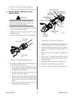
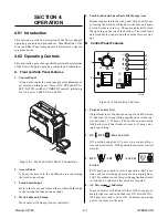
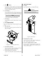
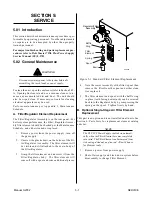
C. Torch Bulkhead Panel
The torch bulkhead panel is located under the access
panel.
1. Pilot Lead Stud
Stud used to connect the Torch Leads Pilot Lead to
the Power Supply.
2
1
3
A-00923
Figure 4-3 Torch Panel Connections
2. Control Cable Connector
Used to interface the Adapter (supplied with Power
Supply) to the Torch Leads Control Cable.
3. Negative/Plasma Lead Connection
Connects the torch negative/plasma lead to the unit.
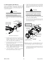
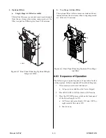
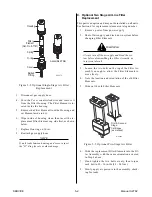
D. Rear Panel Features
1. Gas Input
Input connection for air or nitrogen (N2) input.
WARNING
This unit not to be used with oxygen (O
2
).
1
2
3
A-02605
Figure 4-4 Rear Panel
2. Primary Input Power Cable
Primary input power cable capable of handling the
input voltage designed for this unit.
3. Gas Pressure Regulator/Filter Assembly
Pressure regulator to adjust the input gas pressure to
the Power Supply. An air line filter is supplied as part
of the pressure regulator.
Summary of Contents for CE PAKMaster 75 XL Plus
Page 2: ......
Page 6: ......
Page 28: ...INSTALLATION 3 12 Manual 0 2782 ...
Page 47: ...Manual 0 2782 A 5 APPENDIX This page left blank ...
Page 48: ...APPENDIX A 6 Manual 0 2782 APPENDIX 5 SYSTEM SCHEMATIC A 02638 ...
Page 49: ...Manual 0 2782 A 7 APPENDIX A 02638 ...
Page 50: ......