


INSTALLATION
3-10
Manual 0-2782
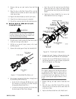
4. The plasma power supply work cable (see NOTE) is
connected to the cutting table at the single point “Star”
ground.
NOTE
Do Not connect the work cable directly to the
ground rod.
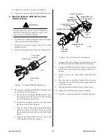
5. Make sure work cable and ground cables are prop-
erly connected. The work cable must have a solid
connection to the cutting table. The work and ground
connections must be free from rust, dirt, grease, oil
and paint. If necessary grind or sand down to bare
metal. Use lock washers to keep the connections tight.
Using electrical joint compound to prevent corrosion
is also recommended.
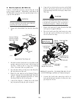
6. The plasma power supply chassis is connected to the
power distribution system ground as required by elec-
trical codes. If the plasma supply is close to the cut-
ting table (see NOTE) a second ground rod is not usu-
ally needed, in fact it could be detrimental as it can
set up ground loop currents that cause interference.
When the plasma power supply is far away from the
ground rod and interference is experienced, it may
help to install a second earth ground rod next to the
plasma power supply. The plasma power supply
chassis would then be connected to this ground rod.
NOTE
It is recommended that the Plasma Power Supply
be within 20 - 30 ft (6.1 – 9.1 m) of the cutting
table, if possible.
7. The plasma control cable should be shielded with the
shield connected only at the cutting machine end.
Connecting the shield at both ends will allow ground
loop currents which may cause more interference than
with no shield at all.
C. Creating An Earth Ground
1. To create a solid, low resistance, earth ground, drive a
1/2 in (12 mm) or greater diameter copper clad ground
rod at least 6 - 8 ft (1.8 - 2.4 m) into the earth so that
the rod contacts moist soil over most of its length.
Depending on location, a greater depth may be re-
quired to obtain a low resistance ground (see NOTE).
Ground rods, typically 10 ft (3.0 m) long, may be
welded end to end for greater lengths. Locate the rod
as close as possible to the work table. Install a ground
wire, 1/0 AWG (European 50 mm
2
) or greater, between
the ground rod and the star ground point on the cut-
ting table.
NOTE
Ideally, a properly installed ground rod will have a
resistance of three ohms or less.
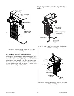
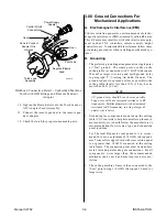
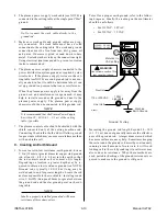
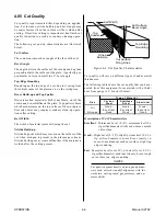
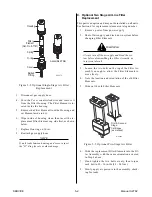
To test for a proper earth ground, refer to the follow-
ing diagram. Ideally, the reading on the multimeter
should be as follows:
• For 115VAC: 3.0 VAC
• For 230VAC: 1.5 VAC
A-02971
+
_
Meter set to
VAC setting
Machine
Earth Ground
Neutral
Line (Hot)
100W
Light Bulb
115 or 230VAC
WARNING
Use extreme caution. This
test uses live voltage.
115VAC: 3.0 VAC
230VAC: 1.5 VAC
V
~
V
~
VR COM A
Ground Testing
2. Increasing the ground rod length beyond 20 - 30 ft
(6.1 – 9.1 m) does not generally increase the effective-
ness of the ground rod. A larger diameter rod which
has more surface area may help. Sometimes keeping
the soil around the ground rod moist by continuously
running a small amount of water into it will work.
Adding salt to the soil by soaking it in salt water may
also reduce its resistance. When these methods are
used, periodic checking of the ground resistance is re-
quired to make sure the ground is still good.
Summary of Contents for CE PAKMaster 75 XL Plus
Page 2: ......
Page 6: ......
Page 28: ...INSTALLATION 3 12 Manual 0 2782 ...
Page 47: ...Manual 0 2782 A 5 APPENDIX This page left blank ...
Page 48: ...APPENDIX A 6 Manual 0 2782 APPENDIX 5 SYSTEM SCHEMATIC A 02638 ...
Page 49: ...Manual 0 2782 A 7 APPENDIX A 02638 ...
Page 50: ......