


INSTALLATION
3-4
Manual 0-2782
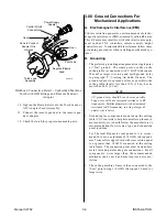
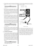
E. Using High Pressure Gas Cylinders
1. Refer to the following when using high pressure gas
cylinders as the gas supply:
CAUTION
Pressure should be set at 100 psi (6.9 bar) at the
high pressure gas cylinder regulator.
a.
Refer to the manufacturer’s specifications for in-
stallation and maintenance procedures for high
pressure gas regulators.
b. Examine the cylinder valves to be sure they are
clean and free of oil, grease or any foreign mate-
rial. Momentarily open each cylinder valve to blow
out any dust which may be present.
c.
The cylinder must be equipped with an adjustable
high-pressure regulator capable of outlet pressures
up to 100 psi (6.9 bar) maximum and flows of up
to 300 scfh (141.5 lpm).
NOTE
Supply hose must be at least #4 hose (1/4 in or 6
mm I.D.).
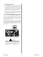
3.07 Connecting Torch Leads
CAUTION
This system is designed for use with the PCH/M-
102, SL60, or SL100 torches only. Do not connect
any other torch to this power supply.
The instructions for connecting the Torch Leads to the
Power Supply are different depending on the type of
leads. This sub-section covers connecting the Torch for
the following applications:
A. Hand Systems
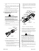
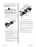
B. Machine Systems (Unshielded Leads)
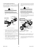
C. Machine Systems (Shielded Leads)
The Torch Leads must be properly installed to the Power
Supply for proper operation. If the torch leads were not
factory-installed, make all torch connections to the Torch
Bulkhead Panel for the desired application.
NOTE
Equipment ordered as a system will have the Torch
factory connected to the Power Supply.
A. Hand Systems
WARNING
Disconnect primary power at the source before as-
sembling or disassembling the power supply, torch
parts, or torch and leads assemblies.
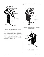
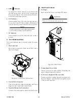
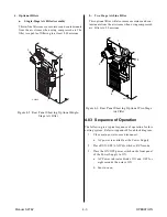
1.
Turn the screw latch securing the front access panel
to the power supply front panel.
Access
Panel
Screw
Latch
A-02467
Figure 3-4 Front Access Panel
2.
Lift the access panel to gain access to the torch
bulkhead panel.
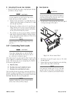
3.
Remove the securing nut from the strain relief sup-
plied on the end of the Torch Leads.
NOTE
The leads may include a pair of wires connected
together and covered with an insulating sleeve.
These wires must remain connected and insulated.
Summary of Contents for CE PAKMaster 75 XL Plus
Page 2: ......
Page 6: ......
Page 28: ...INSTALLATION 3 12 Manual 0 2782 ...
Page 47: ...Manual 0 2782 A 5 APPENDIX This page left blank ...
Page 48: ...APPENDIX A 6 Manual 0 2782 APPENDIX 5 SYSTEM SCHEMATIC A 02638 ...
Page 49: ...Manual 0 2782 A 7 APPENDIX A 02638 ...
Page 50: ......