


Manual 0-2782
3-5
INSTALLATION
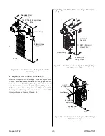
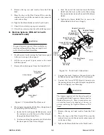
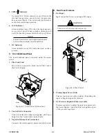
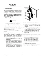
Retaining Nut
Strain Relief
Torch Leads
Assembly
A-02836
Figure 3-5a Torch Strain Relief Nut (Leads with
Two Control Wires)
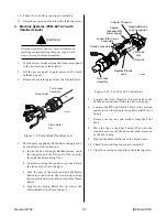
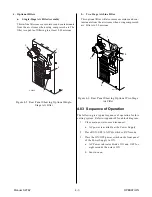
Strain Relief
Nut
Strain Relief
Torch Leads
Assembly
A-03607
Negative /
Plasma Lead
Pilot Lead
Figure 3-5b Torch Strain Relief Nut (Leads with
Four Control Wires)
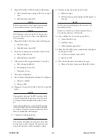
4.
Feed the torch lead ends and the Strain Relief into
the hole in the unit.
5.
Secure the Strain Relief with the retaining nut re-
moved earlier.
6.
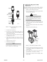
Connect the torch Negative/Plasma Lead to the
bulkhead connection inside the Power Supply.
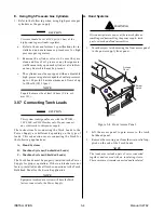
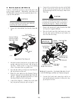
Adapter
(Supplied With
Power Supply)
Pilot Lead
Torch Lead
Assembly
Negative/Plasma
Lead
Adapter
Connector
Pilot Lead Stud
Negative/Plasma Lead
Connection
A-02825
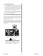
Control (PIP) Circuit
Connectors
Figure 3-6a Torch Lead Connections (Leads with
Two Control Wires)
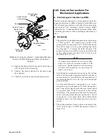
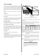
Pilot Lead
Torch Lead
Assembly
Negative/Plasma
Lead
Adapter
Connector
Pilot Lead Stud
Negative/Plasma
Lead Connection
A-03608
Note: Actual Bulkhead
configuration may
differ from that shown.
Adapter
Control Circuit
Connectors
Figure 3-6b Torch Lead Connections (Leads with
Four Control Wires)
7.
Connect the Control Cables to the mating connec-
tors on the Adapter supplied on the Power Sup-
ply.
Summary of Contents for CE PAKMaster 75 XL Plus
Page 2: ......
Page 6: ......
Page 28: ...INSTALLATION 3 12 Manual 0 2782 ...
Page 47: ...Manual 0 2782 A 5 APPENDIX This page left blank ...
Page 48: ...APPENDIX A 6 Manual 0 2782 APPENDIX 5 SYSTEM SCHEMATIC A 02638 ...
Page 49: ...Manual 0 2782 A 7 APPENDIX A 02638 ...
Page 50: ......