3
Chillers designed for use with a remote air-cooled
condenser and the remote condensers themselves
ship with a nitrogen holding charge. Check the
remote condenser for signs of leaks prior to rigging.
This will ensure no coil damage has occurred after
the unit left the factory. The condenser ships with
the legs removed. Mount the legs to the condenser
using the provided nuts, bolts, and washers.
Unit Storage
When storing the unit it is important to protect it
from damage. Blow out any water from the unit;
cover it to keep dirt and debris from accumulating or
getting in, and store in an indoor sheltered area that
does not exceed 145°F.
Installation - Chiller
Unit Location
The unit is available in many different configurations
for various outdoor environments. Refer to the
proposal and order acknowledgement document for
the equipment to verify the specific design
conditions in which it can operate. When considering
where to locate the unit, consult the local code
requirements as well as the NEC (National Electrical
Code).
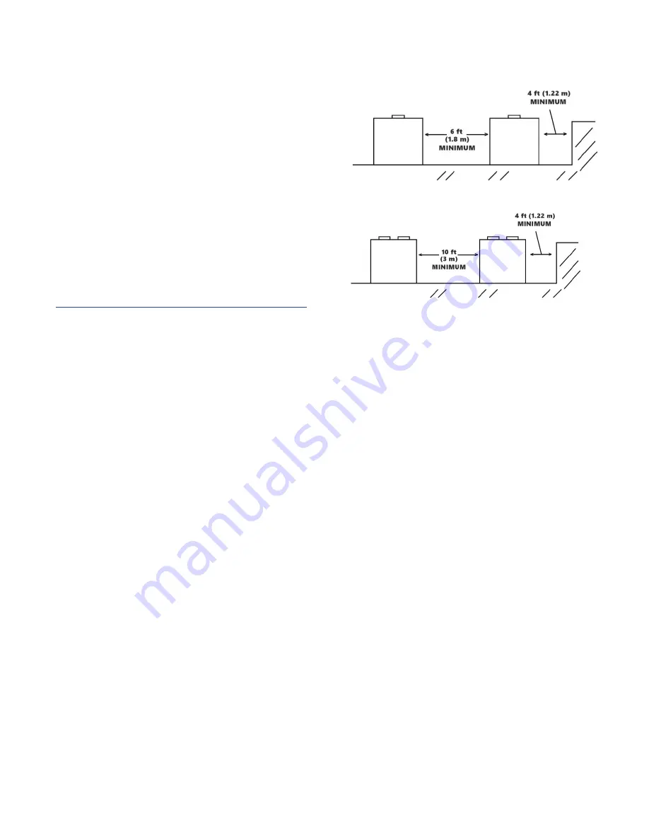
To ensure proper airflow and clearance space for
proper operation and maintenance, ensure the
condenser airflow is unrestricted on both the inlet
and outlet of the chiller. Refer to Figure 1 and
Figure 2 for minimum allowable clearance around
the chiller and to minimize the potential for air
recirculation. It is acceptable to reduce the clearance
on the control panel side to 4 feet while still meeting
NEC code and without impeding performance. When
installing multiple chillers in the same location, the
minimum separation between the sides of the
chillers may be reduced to 6 feet without sacrificing
performance provided the remaining sides are
unrestricted. For acceptable clearance with layout
involving more than two chillers, please contact
factory. Avoid locating piping or conduit over the
unit to ensure easy access with an overhead crane or
lift to lift out heavier components during
replacement or service.
Consider locating the condenser where fan noise
and vibration transmission into nearby workspaces is
unlikely.
Figure 1 – KSE 40 to 60 Unit Location
Figure 2 – KSE 80 to 120 Unit Location
Mounting Foundation
Install the unit on a rigid, non-warping mounting
pad, concrete foundation, or level floor suitable to
support the full operating weight of the equipment.
When installed the equipment must be level within
¼ inch over its length and width. When vibration
isolators are required, mount them at the locations
shown in.Figure 3.
Rigging
The chiller has a frame to facilitate easy movement
and positioning with a crane provided proper lifting
bars, spreader bars, and rigging is used. Use
spreader bars to keep cables or chains clear of the
unit frame and sides. Follow proper rigging methods
to prevent damage to components. Avoid impact
loading caused by sudden jerking when lifting or
lowering the chiller. Use pads where abrasive surface
contact may occur as shown in Figure 4.
Summary of Contents for Accuchiller KSE
Page 1: ......
Page 2: ......
Page 10: ...4 Figure 3 Mounting Platform Figure 4 Rigging...
Page 37: ...31 Notes...
Page 38: ...32...
Page 39: ......


