background image

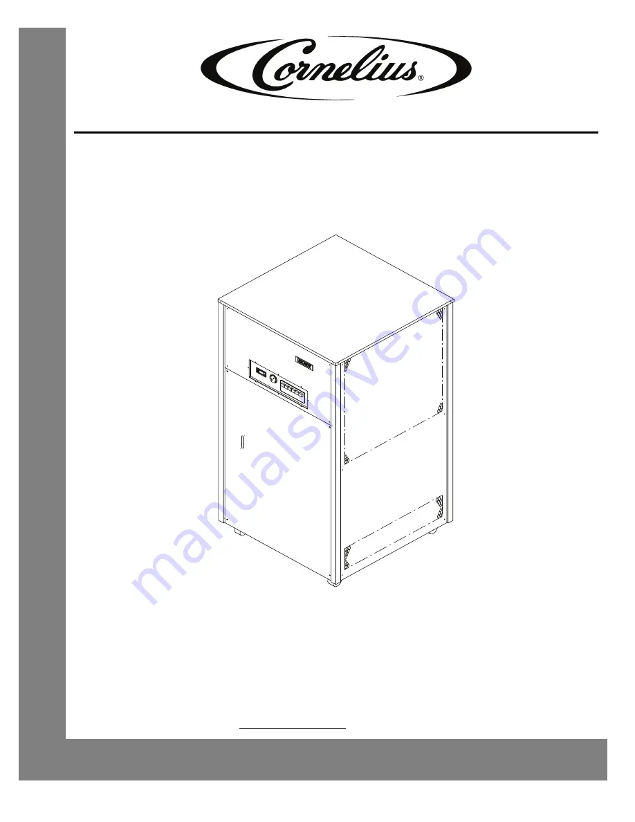
CHILLER MODEL: CH1500, 2000 AND 3000

Operator’s & Installation Manual

Release Date: February 12, 2010

Publication Number: 621055837OPR

Revision Date: March 25, 2014

Revision: E

Visit the Cornelius web site at www.cornelius.com for all your Literature needs.

Summary of Contents for CH1500

Page 1: ...000 AND 3000 Operator s Installation Manual Release Date February 12 2010 Publication Number 621055837OPR Revision Date March 25 2014 Revision E Visit the Cornelius web site at www cornelius com for all your Literature needs ...

Page 2: ...occurrences including but not limited to 1 other than normal and proper use and normal service conditions with respect to the Product 2 improper voltage 3 inadequate wiring 4 abuse 5 accident 6 alteration 7 misuse 8 neglect 9 unauthorized repair or the failure to utilize suitably qualified and trained per sons to perform service and or repair of the Product 10 improper cleaning 11 failure to follo...

Page 3: ...er with Reservoir 5 Chiller without Reservoir 5 Start up 7 Water Flow Start Up 7 Chiller with Pump 7 Chiller without Pump 7 Thermostat 7 Standard Thermostat Eliwell IC902 7 Thermostat Dual Set Point 8 Dual Point Adjustment 8 Cooling Start Up 8 Control Panel 9 Maintenance 10 Fluid Recommendations 10 Safety Controls 11 High Pressure Control HPC 11 Low Temperature Control LTC 11 Low Pressure Control ...

Page 4: ......

Page 5: ... minor or moderate injury or equipment damage SAFETY TIPS Carefullyreadandfollowall safety messages inthismanualandsafety signsontheunit Keepsafety signsin goodconditionandreplace missingordamageditems Learnhowtooperatetheunitandhow to usethe controls properly Do notletanyoneoperate theunitwithoutpropertraining This applianceisnot intendedforuse by very young children or infirmpersonswithoutsuperv...

Page 6: ... power is off to the unit before any work is performed Failure to disconnect the power could result in serious injury death or equipment damage CAUTION Always be sure to keep area around the unit clean and free of clutter Failure to keep this area clean may result in injury or equipment damage SHIPPING AND STORAGE CAUTION Before shipping storing or relocating the unit the unit must be sanitized an...

Page 7: ...d cooling capacity are listed for air cooled units with a circulation temperature of 68 F and ambient temperature of 80 F and standard pump 2 Cooling capacity will be affected as follows Derate 17 for 50 Hz operation Derate 1 for each degree Fahrenheit drop in recirculating temperature Derate 0 5 for each degree Far en he it increase in ambient temperature 3 The operating water temperature range f...

Page 8: ...ectrical conduit to a properly fused disconnect of proper amperage or wired to a properly rated power cord and plugged into an outlet with the appropriate disconnect and amperage rating The electrical junction box located on the upper rear of the chiller includes a four terminal strip for power supply connections The DATA PLATE located beside the junction box indicates the actual phase voltage and...

Page 9: ...to prevent condensation and or significant liquid heat loss Chiller with Reservoir The reservoir can be filled by removing the water fill cap located on the upper rear of the Chiller See Fluid Recommendations After ensuring that the drain valve is closed fill the reservoir via the full port with clean water until the water level sight glass on the front of the unit indicates FULL the fill cap shou...

Page 10: ... Installation Manual Publication Number 621055837OPR 6 2010 2014 Cornelius Inc Figure 4 Chiller Plumbing Schematic no Pump no Tank Option CHILLER INLET FROM PROCESS EVAPORATOR T E L T U O R E L L I H C L O R T N O C P M E T W O L TO PROCESS ...

Page 11: ...otor and or piping If this valve requires adjustment please contact the factory for proper setting procedure and pressures A flow meter and throttling valve can be added in the chiller inlet line in order to monitor and or adjust the flow rate through the chiller Once the flow has been established the thermostat can be adjusted to the desired set point Chiller without Pump A flow meter and throttl...

Page 12: ...e is 40o F 5o C to 100o F 38o C If operation outside of this range is required please contact the Technical Service Department Figure 6 Eliwel IC 915 Dual Point Thermostat COOLING START UP Once flow is established and the thermostat is set to the desired set point turn the control power switch to ON press in All alarm indicators should be extinguished and the Chiller refrigeration system will cycl...

Page 13: ...te This switch must be pressed in for the Chiller to operate 3 COOLING LIGHT A green light that indicates refrigeration system operation This light cycles on and off in response to the thermostat 4 HIGH PRESSURE ALARM LIGHT A red light that indicates high refrigeration pressure 5 LOW PRESSURE ALARM LIGHT A red light that indicates low refrigeration pressure 6 LOW TEMPERATURE ALARM LIGHT A red ligh...

Page 14: ... build up and possible restriction of flow by contaminates 4 The strainer at the Chiller inlet should be removed and cleaned monthly field installed FLUID RECOMMENDATIONS Chillers are designed to operate with water to provide maximum performance for temperatures of 50o F 100o F Table 2 Distilled Water Acceptable De Ionized Water 1 5 MEG OHMS Acceptable De Ionized Water 5 MEG OHMS Acceptable with S...

Page 15: ...n the event that the fluid inside the evaporator falls below 35o F If this occurs check the following 1 That the thermostat set point is set at 40o F or greater 2 That the flow through the system is greater than two gallons per minute This control is mounted in the lower left hand corner of the electrical box It automatically resets itself once the water temperature is restored to 38 F The low tem...

Page 16: ...pump power switch C Defective control transformer A Turn the pump power switch to the ON position B Replace the switch C Replace the transformer Pump does not operate Pump power light ON A No water in reservoir B Restriction in the line to or from the chiller C Open or defective pump overload relay D Defective pump contactor E Defective pump motor or damaged impeller A Fill reservoir B Remove rest...

Page 17: ...sure that there is adequate flow through piping to condenser High pressure alarm light is ON A Restricted condenser airflow B Defective condenser fan and or motor C Defective expansion valve D Low or no condenser water flow A Clean the fins of the condenser and ensure that the air flow is not restricted B Check to ensure that the fan blade is not blocked Replace the fan motor if necessary C Replac...

Page 18: ...on is found on the data plate The Model and Serial Number are also needed when ordering replacement parts Figure 7 Unit Data Label REFRIGERATION DIAGRAM Figure 8 Refrigeration Piping Schematic with Hot Gas Bypass REMCOR PRODUCTS COMPANY GLENDALE HEIGHTS IL 60139 2268 MODEL NO SERIAL NO PART NO V OLTS AMPS R134A HZ PH MADE I N U S A BAR CODE TXV E QUALIZE R LINE TXV S E NS ING B ULB TXV E VAPOR ATO...

Page 19: ...2R Lower Front Panel 8 6200498515 Lid 9 27585R Control Panel 10 22870 FPT Coupling 11 32386 Digital Thermostat 33319 Control Temp Dual Set Point 12 32989 Electric Box Assembly 13 31299 Fan 14 31298 Motor Fan 230Volt 31698 Motor Fan 460Volt CH3000 15 620311601 Switch Push Button 16 620311605 Red Indicator 17 620311606 Green Indicator 18 620049520 Comp Danfoss MTZ 028 1 5HP CH1500 620049393 Comp Dan...

Page 20: ...85 Evap Asy Foamed CH2000 61085 Evap Asy CH3000 23 61089 Condenser 60983 Cond CH2000 61090 Cond CH3000 Air Cool 25 60685 Receiver 26 70893 Caster 27 620049517 Panel Right Side Item No Part No Name 28 70923 Handle Removable Panel NS 61083Q9171 Cond Asy Foamed CH1500 60985 Evap Asy Foamed CH2000 61085 Evap Asy Foamed CH3000 NS 40122 Valve Water Reg 40199 Valve Water Regulating CH3000 Item No Part No...

Page 21: ...PUMP TANK ASSEMBLY 1 2 3 4 5 Figure 11 Pump Tank Exploded View Table 4 Pump Tank Components Item No Part No Name 1 15404R Thermowell Temperature Control 2 32589 Temperature Probe 3 51096 Tank Assembly 4 620408104 Pump 620710601 Pump CH2000 CH3000 5 40646 Valve By Pass Call the Service Dept for proper pump identification ...

Page 22: ...6 Electrical Box Assembly Item No Part No Name 1 31001 Low Temperature Thermostat 2 32804 Control Transformer 3 32992 Contactor Compressor 4 60501 High Pressure Control 5 60502 Low Pressure Control 6 620314008 Contactor Pump 7 620314002 Overload Relay 1 0 to 1 4A 620314003 Overload Relay 1 3 to 1 8A 620314005 Overload Relay 2 2 to 3 1A 620314006 Overload Relay 2 8 to 4 0A 620314007 Overload Relay ...

Page 23: ...CH1500 CH2000 CH3000 Chiller Operator s Installation Manual 2010 2014 Cornelius Inc 19 Publication Number 621055837OPR WIRING DIAGRAM Figure 10 ...

Page 24: ...CH1500 CH2000 CH3000 Chiller Operator s Installation Manual Publication Number 621055837OPR 20 2010 2014 Cornelius Inc ...

Page 25: ......

Page 26: ...Cornelius Inc www cornelius com ...

Reviews: