DLC-250.4 LOUDSPEAKER CONTROLLER
15
Configuration
D
iagr
am 5k
Signal
F
lo
w
S
chema
tic
(four
output
amplifier
)
A
n
al
o
g
3
O
ut
pu
t
M
at
rix
Zones A - D
Outputs 1 - 4
A
n
al
o
g
2
Input
Sensitivity
A
n
al
o
g
1
Input
Gain
Input
Sensitivity
Input
Gain
Input
Sensitivity
Input
Gain
A
n
al
o
g
4
SP
D
IF
(stereo)
SP
D
IF Out
(stereo).
Zones A (left) and B (right)
Pink Noise
G
ai
n
D
el
ay
Le
ve
l
Adjustment
Le
ve
l
Adjustment
Le
ve
l
Adjustment
Le
ve
l
Adjustment
Compressor
Compressor
Compressor
Compressor
D
el
ay
D
el
ay
D
el
ay
EQ
EQ
EQ
EQ
EQ
EQ
EQ
EQ
FIR
FIR
FIR
FIR
Polarity
Polarity
Polarity
Polarity
Limiter
BTL
Amplifier
2 x Low-Z
1 x Hi-Z
BTL
Amplifier
2 x Low-Z
1 x Hi-Z
Limiter
Limiter
Limiter
Driver
Alignment
Driver
Alignment
Driver
Alignment
Driver
Alignment
Crossover
Crossover
Crossover
Crossover
G
ai
n
Tr
im
G
ai
n
Tr
im
G
ai
n
Tr
im
G
ai
n
Tr
im
Input
Sensitivity
Input
Gain
Input
Gain
Input
Selection
Input S
etup
Zone S
etup & Routing
O
utput S
etup
Output
1
Output
2
Output
3
Output
4
Zone A
djustmen
t P
ar
amet
ers
Sp
eak
er P
reset P
ar
amet
ers
•
The
LAN
menu enables configuration and reset of the wired network
options and parameters.
•
The
WiFi
menu enables configuration and reset of the wireless network
options and parameters.
5.4 Setup and Signal Routing
Thanks to their network based configuration features, THEORY DLC
amplifiers offer considerable versatility in terms of sources, signal routing,
installation zones and output modes. Inputs can be freely assigned to
installation zones, and those zones assigned freely to the available amplifier
outputs in either Lo-Z or Hi-Z modes.
This versatility enables, for example, one amplifier simultaneously to drive
both Lo-Z and Hi-Z speakers, or for different inputs to be routed to different
output zones.
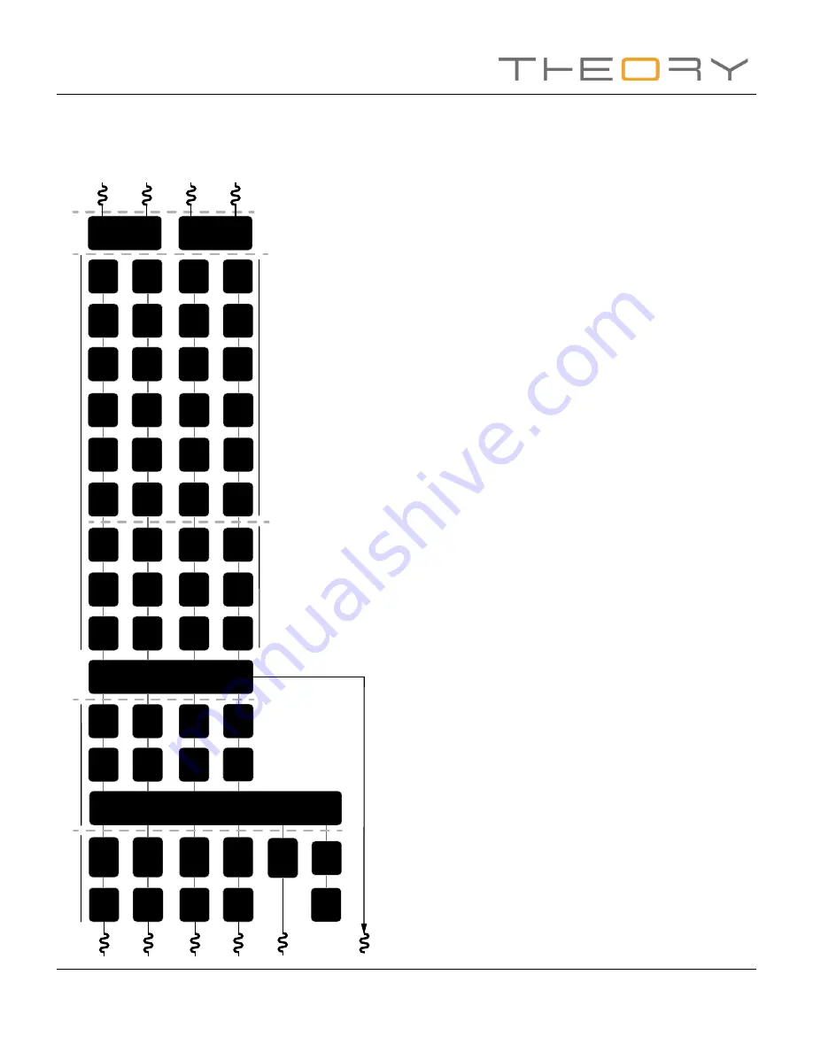
The following paragraphs describe and illustrate the recommended
procedure for configuring input, zone and output routing. A general signal
flow schematic is also illustrated in
Diagram 5k.
5.4.1 Input Setup
Open the configuration Dashboard and select the
Input Tab
. The Input Tab
is shown in
Diagram 5b.
• To edit default input names simply select and type in the Input
Name field.
• Define a mono or stereo input by selecting the appropriate
option. Defining a stereo input will reduce the total number of
discrete inputs available.
• Select an input sensitivity option from the drop-down menu:
+14dB, +4dB, -10dB and ‘microphone’ options are available.
Generally, the +14dB or +4dB options are appropriate for
‘professional audio’ source hardware with balanced outputs,
while the -10dB option is more appropriate for ‘consumer
audio’ source hardware with unbalanced outputs. The
‘microphone’ option provides the significantly greater sensitivity
required for microphones.
Note: Only dynamic microphones are suitable for
connection. Phantom power for condenser microphones
is not provided.


