Page 6
CL-B101D40HZ Manual (d0098)
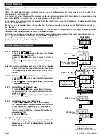
Example of Using the Center Point Bargraph Display Mode
with a Unipolar Input
If the meter's full scale range is set to 5000 counts, the midpoint would
be 2500 counts. If a signal of 2500 counts is applied only one segment at
the 2500 count mark will light up. If a signal of 4000 counts is applied the
segments between the center segment (2500 counts) and the 4000 count
mark light up.
If a signal of 1000 counts is applied, the segments between the center seg
-
ment (2500 counts) and the 1000 count mark will light up.
Example of Using the Center Point Bargraph Display Mode
with Bipolar Signal Inputs
The
meter
may also be calibrated to display symmetrical bipolar signals such
as ± 1 V or ± 10 V. When the center point display mode is selected, it will
then function as a center zero meter. When positive signals are applied, the
bar will go up from the center point, and when negative signals are applied,
the bar will go down from the center point.
STEP E Selecting the [Anhi] Digital Value for Analog High Output
1) Using the and buttons, adjust the display to the desired
digital value at which the [chi] Calibrated Analog High output will
occur. For digital readings outside the digital span selected, the
analog output will linearly rise above the value set for chi, up to the
maximum analog output capability. However, the analog output will
not go lower than the calibrated value set for cLo (see below).
2) Press the
P
button. Display toggles between [AnLo] and
previous [AnLo] setting.
STEP F Selecting the [AnLo] Digital Value for Analog Low Output
1) Using the and buttons, adjust the display to the desired
digital value at which the [cLo] Calibrated Analog Low output will
occur.
For Digital readings outside the Digital Span selected, the
analog output will not go lower than the calibrated value set for
cLo.
2) Press the
P
button. The display toggles between [cto] and
[oFF].
Note:
Any two digital span points from –1999 to 9999 can be selected. The digital
values for [Anhi] analog high and [AnLo] analog low can be reversed to provide a 20 to
4mA output. The digital span selected can be as small as two counts, when using the
analog output to function as a Control or Alarm Driver. Small digital spans will cause
the high resolution 16 bit D to A to increment digitally in stair case steps.
Digital Span Selection for Analog Range Output
Digital Span Selection for Analog Range Output
Bargraph Center Point Display Mode Selection
STEP G Bargraph Center Point Mode Selection (See example above)
1) To select bargraph center point mode, press the or
button. Display changes from [oFF] to [on].
2) Press the
P
button. Display toggles between [diSP] and
[on] or [oFF].
STEP H Digital Display ON/OFF Selection
1) To set the display to [oFF], press the
or button.
Display toggles between [diSP] and [oFF].
2) Press the
P
button. The display exits the calibration mode
and returns to the operational display. Only the bargraph
display is on and the digital display is off.
If the digital display is selected to be off, pressing any button to
make programming changes or to view setpoints activates the digital display.
When the procedure is complete, the digital display will then automatically
switch off.
The Display/Bargraph settings are now complete.
Operational Display
STEP G
STEP H
See Example of Bargraph
Center Point Display Mode
Selection Above
From Digital Span Selection
for Analog Range Output Above
or Direct From Decimal Point
and Brightness Selection Page 5
if Analog Output Option is Not Present
BARGRAPH CENTER POINT
DISPLAY MODE SELECTION
STEP E
STEP F
This branch will only
appear if the analog
output option is installed
To Bargraph Center
Point Display Mode
Selection Below
From Decimal Point and
Brightness Selection
See Page 5
DIGITAL SPAN SELECTION
FOR ANALOG RANGE OUTPUT
-1V
+1V
0V
-1V
+1V
0.800
-0.800
0V
-1V
+1V
0V
Center Point
Single Bar Lit
Center Point
As signal
increases
Digital display
Digital display
Center Point
As signal
decreases
Digital display
0
5000
5000
2500
2500
4000
0
5000
2500
1000
0
Center Point
Single Bar Lit
Center Point
As signal
increases
Digital display
Digital display
Center Point
As signal
decreases
Digital display
Unipolar Signal Input
Bipolar Signal Input


