


L M K 0 4 9 0 6 E V A L U A T I O N B O A R D O P E R A T I N G I N S T R U C T I O N S
SNAU126
14
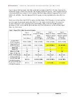
Connector Name
Signal Type,
Input/Output
Description
Populated:
OSCout0, OSCout0*,
Analog,
Output
Buffered outputs of OSCin port.
The output terminations on the evaluation board are
shown below, the output type selected by default in
CodeLoader is indicated by an asterisk (*):
OSC output pair
Default Board
Termination
OSCout0
LVDS* / LVCMOS
OSCout0 has a programmable LVDS, LVPECL, or
LVCMOS output buffer. The OSCout0 buffer type can
be selected in CodeLoader on the
Clock Outputs
tab
via the OSCout0_TYPE control.
OSCout0 is AC-coupled to allow safe testing with RF
test equipment.
If OSCout0 is programmed as LVCMOS, each output
can be independently configured (normal, inverted,
inverted, and off/tri-state).
Vcc
Power,
Input
Main power supply input for the evaluation board.
A 3.9 V DC power source applied to this SMA will, by
default, source the onboard LDO regulators that power
the inner layer planes that supply the LMK04906B and
its auxiliary circuits (e.g. VCXO).
The LMK04906B contains internal voltage regulators
for the VCO, PLL and other internal blocks. The clock
outputs do not have an internal regulator, so a clean
power supply with sufficient output current capability
is required for optimal performance.
On-board LDO regulators and 0 resistor options
provide flexibility to supply and route power to various
devices. See schematics for more details.
Populated:
J1
Power,
Input
Alternative power supply input for the evaluation board
using two unshielded wires (Vcc and GND).
Apply power to either Vcc SMA or J1, but not both.
Unpopulated:
VccVCO/Aux
Power,
Input
Optional Vcc input to power the VCO circuit if
separated voltage rails are needed. The VccVCO/Aux
input can power these circuits directly or supply the on-
board LDO regulators. 0 Ω resistor options provide
flexibility to route power.


