PRGM LOAD
CFG3
CFG4
CFG2
CFG1
J10
J11
LO
LO
LO
LO
HI
HI
HI
HI
3.3
LEDs
Hardware Configuration
www.ti.com
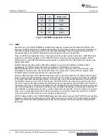
Figure 3. EEPROM Configuration Options
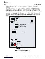
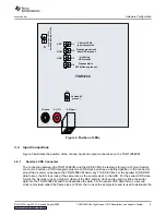
Six LEDs are on the TSW1200EVM to indicate the presence of power and the state of the FPGA. See
Figure 4. LED D16 illuminates to indicate the presence of a 6-V power supply to the board. On power up,
the FPGA loads its programming bit file from the FPGA EEPROM. Once the programming bit file has
completed loading, the LED D7 illuminates to indicate that the FPGA is operational.
Once the FPGA has loaded its bit file, it internally resets the clock circuitry that locks to a 200-MHz clock
signal from a 200-MHz oscillator on the TSW1200 board. Once the internal reset is complete, LED D1
(labeled ADC on the TSW1200 silkscreen) illuminates to indicate that the TSW1200EVM is ready to use
with an ADC EVM.
LED D4 flashes when the onboard 200-MHz oscillator is running. The 200-MHz oscillator clock is
multiplied up to 250 MHz within the FPGA. The pattern of the flashing is of the form
flash-flash-pause-pause. That is, the LED illuminates for a time, then turns off for the same time, then
illuminates for the same time, then turns off 5 times. The internal time is derived from a division of the
250-MHz reference clock derived from the onboard oscillator.
LED D2 (labeled DCM on the TSW1200 silkscreen, which is an abbreviation for the digital clock manager
block of logic in the FPGA) flashes when an LVDS clock from the ADC is present. The DCM clock flashes
in the same flash-flash-pause-pause pattern, using the same clock division parameters as were used for
the 250-MHz reference clock LED. In this manner, the DCM LED can be used to see that the clock from
the ADC is present and approximately the right frequency by comparing it to the 250-MHz LED. That is, if
the sample rate clock to the ADC is 250 MHz, then the DCM LED and the 250-MHz LED flash at the same
rate. If the sample clock to the ADC is 125 MHz, then the DCM LED flashes at half the rate of LED D4. If
the DCM LED is not flashing at all, then no clock is detected from the ADC. Common reasons for an ADC
clock not to be detected are that the EVM is not powered on, or that the clock from the ADC is a CMOS
clock instead of an LVDS clock due to an improper jumper setting.
LED D3 (labeled USB on the TSW1200EVM silkscreen) illuminates whenever the TSW1200 user interface
software is accessing the FPGA by way of the USB connection. For longer FFT record lengths and lower
UART baud rates, the USB LED illuminates longer than for shorter FFT record lengths or higher UART
baud rates.
8
TSW1200EVM: High-Speed LVDS Deserializer and Analysis System
SLAU212A – April 2007 – Revised August 2008


