


EPWM1SYNCO
ePWM1
EPWM1SYNCI
GPIO
MUX
SYNCI
eCAP1
EPWM2SYNCI
ePWM2
EPWM2SYNCO
EPWM3SYNCO
ePWM3
EPWM3SYNCI
EPWM4SYNCI
ePWM4
EPWM4SYNCO
EPWM5SYNCO
ePWM5
EPWM5SYNCI
ePWM6
EPWM6SYNCI
eCAP4
EPWM7SYNCI
ePWM7
EPWM7SYNCO
EPWM8SYNCI
ePWM8
EPWM8SYNCO
EPWM9SYNCI
ePWM9
www.ti.com
ePWM Submodules
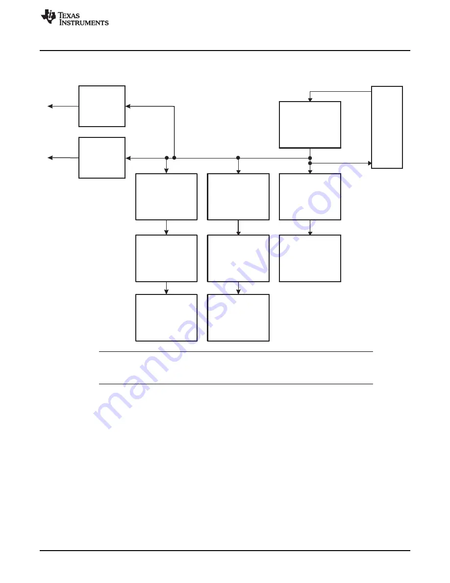
Scheme 3, shown in
, is used by all other devices.
Figure 9. Time-Base Counter Synchronization Scheme 3
NOTE:
All modules shown in the synchronization schemes may not be available on all devices.
Please refer to the device specific data manual to determine which modules are available on
a particular device.
Each ePWM module can be configured to use or ignore the synchronization input. If the TBCTL[PHSEN]
bit is set, then the time-base counter (TBCTR) of the ePWM module will be automatically loaded with the
phase register (TBPHS) contents when one of the following conditions occur:
•
EPWMxSYNCI: Synchronization Input Pulse:
The value of the phase register is loaded into the counter register when an input synchronization pulse
is detected (TBPHS
→
TBCTR). This operation occurs on the next valid time-base clock (TBCLK)
edge.
The delay from internal master module to slave modules is given by:
–
if ( TBCLK = SYSCLKOUT): 2 x SYSCLKOUT
–
if ( TBCLK != SYSCLKOUT):1 TBCLK
•
Software Forced Synchronization Pulse:
Writing a 1 to the TBCTL[SWFSYNC] control bit invokes a software forced synchronization. This pulse
is ORed with the synchronization input signal, and therefore has the same effect as a pulse on
EPWMxSYNCI.
•
This feature enables the ePWM module to be automatically synchronized to the time base of another
27
SPRUG04A – October 2008 – Revised July 2009
TMS320x2833x, 2823x Enhanced Pulse Width Modulator (ePWM) Module
© 2008–2009, Texas Instruments Incorporated


