


t1
V
SYS
0
t2
t3
a) Power Limit
Source Voltage
-
to
Gate -
V
DS
t
ON
V
SYS
P
LIM
V
GATE
V
GSL
V
TH
P
MOSFET
0
I
DS
0
Theory of Operation
13
SNVA481B – October 2011 – Revised January 2020
Copyright © 2011–2020, Texas Instruments Incorporated
AN-2143 LM5064 Evaluation Kit
signal was asserted. They are not reset or cleared by the CLEAR_FAULTS command but rather, they are
re-armed, or readied, to be over-written with new values at the onset of the next SMBA signal assertion.
Note that these telemetry fields and this register are not cumulative. That is, they can only be updated
once after the CLEAR_FAULTS command is issued, and it will be at the first occurrence of the SMBA
assertion following the CLEAR_FAULTS. This allows the user to determine device conditions at the first
occurrence of the SMBA assertion.
12
Theory of Operation
The LM5064 provides intelligent control of the power to a load from a live power source. The three primary
functions of the device are to limit inrush current during turn-on, monitor the load current for faults during
normal operation, and to provide system telemetry for the following parameters: Input Voltage (VCC to
VEE), Input Current (IIN), Input Power (PIN), Output Voltage (VOUT), Auxilliary Voltage (VAUX), and
Temperature. Additional functions include under- and over-voltage lock-outs (UVLO/OVLO) to ensure
voltage is supplied to the load only when the system input voltage is within a specified range, power
limiting of the series pass MOSFET (Q1) during turn-on, and a Power Good logic output (PGD) to indicate
the output voltage status.
Upon applying the input voltage to the LM5064, Q1 is initially held off for the insertion delay (125 ms) to
allow ringing and transients on the input to subside. At the end of the insertion delay, if the input voltage
(VCC-VEE) is above the UVLO threshold, Q1 is turned on in a controlled manner to limit the inrush
current.
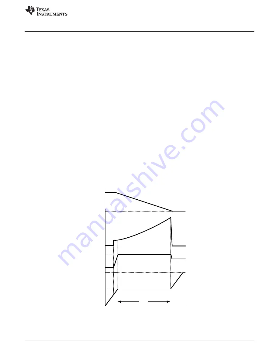
The LM5064 utilizes two methods to limit inrush currents at startup. For the input voltage range and sense
resistor on this board, the inrush current will be limited by the MOSFET power limit method. The power
limit method controls the input current such that a constant power is dissipated by Q1 during startup. At
the onset of the startup period, V
sys
(VEE)= -48V and V
OUT
= 0V. Q1’s power dissipation is limited to a
peak value set by RPWR (80W) by monitoring its drain current (the voltage across RS) and its drain-to-
source voltage. Their product is maintained constant by controlling the drain current as the drain-to-source
voltage decreases (as the output voltage increases). This is shown in the constant power portion of where
the drain current is increasing to I
LIM
.
Figure 12. Power Up Using Power Limit