


73S1209F Data Sheet
DS_1209F_004
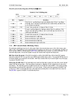
Interrupt Request Register (IRCON): 0xC0
Å
0x00
Table 24: The IRCON Register
MSB
LSB
– –
EX6
IEX5
IEX4
IEX3
IEX2
–
Bit Symbol
Function
IRCON.7 –
IRCON.6 –
IRCON.5
IEX6
External interrupt 6 flag.
IRCON.4
IEX5
External interrupt 5 flag.
IRCON.3
IEX4
External interrupt 4 flag.
IRCON.2
IEX3
External interrupt 3 flag.
IRCON.1
IEX2
External interrupt 2 flag.
IRCON.0 –
1.7.3.3 External
Interrupts
The external interrupts (external to the CPU core) are connected as shown in Table 25. Interrupts with
multiple sources are OR’ed together and individual interrupt source control is provided in XRAM SFRs to
mask the individual interrupt sources and provide the corresponding interrupt flags. Multifunction USR
[7:0] pins control Interrupts 0 and 1. Dedicated external interrupt pins INT2 and INT3 control interrupts 2
and 3. The polarity of interrupts 2 and 3 is programmable in the MPU. Interrupts 4, 5 and 6 have multiple
peripheral sources and are multiplexed to one of these three interrupts. The peripheral functions will be
described in subsequent sections. Generic 80515 MPU literature states that interrupts 4 through 6 are
defined as rising edge sensitive. Thus, the hardware signals attached to interrupts 4, 5 and 6 are
converted to rising edge level by the hardware.
SFR (special function register) enable bits must be set to permit any of these interrupts to occur.
Likewise, each interrupt has its own flag bit that is set by the interrupt hardware and is reset automatically
by the MPU interrupt handler.
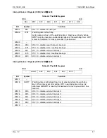
Table 25: External MPU Interrupts
External
Interrupt
Connection Polarity
Flag
Reset
0
USR I/O High Priority
see
1
USR I/O Low Priority
see
2
External Interrupt Pin INT2
Edge selectable
Automatic
3
External Interrupt Pin INT3
Edge selectable
Automatic
4
Smart Card Interrupts
N/A
Automatic
5
USB, RTC and Keypad
N/A
Automatic
6 I
2
C, V
DD
_Fault, Analog
Comp
N/A Automatic
Note 1: Interrupts 4, 5 and 6 have multiple interrupt sources and the flag bits are cleared upon reading of
the corresponding register. To prevent any interrupts from being ignored, the register containing multiple
interrupt flags should be stored temporary to allow each interrupt flag to be tested separately to see which
interrupt(s) is/are pending.
36
Rev.
1.2


