background image

SM 1962 4-00

Section 165-0010

1

BRAKE PARTS - Brake Parts - Rear

SM - 048

DESCRIPTION AND OPERATION

The service brakes are of the calliper disc-type. The
calliper brake head is designed for use with hydraulic
brake fluid. The head is bolted to a mounting plate on
the axle housing. The disc is bolted to the wheel. There
is one brake head and one brake disc at each wheel.

Each calliper brake head assembly consists of a
torque plate, two brake pads, one on each side of the
brake disc, and four brake pistons, two on each side
of the brake disc.

The brake is actuated by hydraulic brake fluid
entering the brake head through one of the bleeder
ports. The piston bores on each side of the torque
plate are interconnected by internal passages.

When the brake is actuated, the hydraulic pressure
forces the pistons against the brake pads which are,
in turn, forced against each side of the brake disc,
slowing or stopping the disc and wheel rotation.

GENERAL INSPECTION

1. Inspect brake pads for wear. If the brake pad
friction material is worn down to 3 mm (0.12 in)
thickness, the pads must be replaced.

2. Inspect brake disc as follows:

a. Measure original thickness of disc at outside
diameter (this area is not contacted by brake pad
friction material).

b. Measure thickness of disc at three points on the
brake pad friction material contact circumference and
determine the average disc thickness.

c. Subtract 'b' from 'a'. If difference is 3 mm (0.12 in)
or greater, the disc must be replaced.

Note: Refer to Section 160-0030, AXLE GROUP
(HUB), for brake disc replacement instructions.

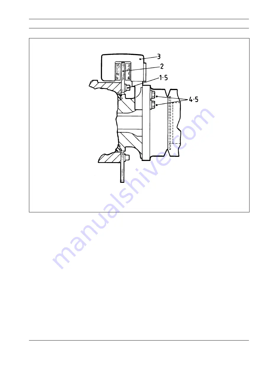
Fig. 1 - Cutaway View of Typical Brake Head and Disc Mounting

1 - Capscrew
2 - Brake Disc

3 - Brake Heads
4 - Bolt

5 - Washer

Courtesy of Machine.Market 

Summary of Contents for TA30

Page 1: ...nance Manual SM 1936 Rev 3 10 02 TECHNICAL PUBLICATIONS DEPARTMENT TEREX EQUIPMENT LIMITED MOTHERWELL SCOTLAND ML1 5RY REF NO SM 799 CLICK HERE FOR TABLE OF CONTENTS CLICK HERE TO RETURN TO MAIN LIBRARY INDEX Courtesy of Machine Market ...

Page 2: ...Courtesy of Machine Market ...

Page 3: ...sidered dangerous but natural rubber and nitrile are non hazardous d If Fluoro elastomer seals have been used then the affected area MUST be decontaminated before undertaking further work e Disposable Heavy Duty Gloves Neoprene MUST be worn and the affected area decontaminated by washing thoroughly with Limewater Calcium Hydroxide solution f Any cloths residue and gloves used MUST be safely discar...

Page 4: ...THIS PAGE IS INTENTIONALLY LEFT BLANK Courtesy of Machine Market ...

Page 5: ...d out or of the possible hazardous consequences of each way Consequently no such broad evaluation has been undertaken Accordingly anyone who uses a service procedure or tool which is not recommended must first satisfy themselves thoroughly that neither their safety nor vehicle safety will be jeopardized by the service method he she selects Two types of heading are used in this manual to attract yo...

Page 6: ...THIS PAGE IS INTENTIONALLY LEFT BLANK Courtesy of Machine Market ...

Page 7: ...ar Drivelines 1534 Rev 1 140 FRONT AXLE GROUP 0020 Axle Group Hub Refer to Section 160 0030 0040 Wheel Rim and Tyre Refer to Section 160 0050 0060 Differential Drive Head Refer to Section 160 0020 150 CENTRE AXLE 0020 Differential Drive Head 1971 160 REAR AXLE GROUP 0020 Differential Drive Head 1969 0030 Axle Group Hub 1968 0050 Wheel Rim and Tyre 1970 165 BRAKE PARTS 0010 Brake Parts Rear 1962 00...

Page 8: ...ick 1953 Rev 2 0121 Pilot Supply Valve 1954 0130 Body Cylinder 1956 250 BRAKING SYSTEM 0000 Air Braking System Schematic 1948 0000 Hydraulic Braking System Schematic 1982 0070 Treadle Valve 1939 0170 Air Tanks and Mounting 1941 0190 Park Emergency Control Valve 1940 0200 Air Drier 1985 Rev 1 0260 Pressure Converter 1508 0270 Air Breather 1509 0280 Relay Emergency Valve 1945 0290 Pressure Protectio...

Page 9: ...rear axles This differential may be locked by the driver for use in difficult traction conditions Standard integral hydraulic retarder which is automatically operated should the engine Fig 1 Machine Dimensions overspeed Blocked filter indicator and filter bypass system provide valve block with additional protection from unfiltered oil Pressures Main 16 2 bar 232 30 lbf in Lockup Wk 14 1 bar 190 15...

Page 10: ...ncy brake control actuates the service brakes Automatic application of service brakes should pressure fall in the brake air system Retardation Hydraulic retarder integral with transmission WHEELS AND TYRES Wheels 5 piece earthmover rims with 12 stud fixing Size Standard 25 x 19 50 in for 23 5 R25 tyres Optional 25 x 22 00 in for 30 65 R25 tyres Tyres Standard 23 5 R25 Optional 30 65 R25 Inflation ...

Page 11: ...ies each 3 5 litres 0 9 US gal Service Brakes 3 litres 0 79 US gal Air Conditioning Compressor 0 125 litres 0 033 US gal TYPICAL NOISE LEVELS Operator Ear ISO 6394 79 dbA Exterior Sound Rating SAE J88 JUN 86 TBA dbA The above result is for the mode giving the highest exterior sound level when measured and operated as per the prescribed procedures of the standard Results shown are for the vehicle i...

Page 12: ...THIS PAGE IS INTENTIONALLY LEFT BLANK Courtesy of Machine Market ...

Page 13: ...elding and flame cutting cadmium plated metals produce odourless fumes which are toxic Recommended industrial hygiene practice for protection of the welding operator from the cadmium fumes and metallic oxides requires enclosure ventilation specifically designed for the welding process A respiratory protective device such as the M S A Gasfoe respirator with G M A cartridge will provide protection a...

Page 14: ...RC AIR gouge or grind out the crack until sound metal is reached If ARC AIR method is employed pre heat area to 200 C 392 F measure 3 4 either side of repair prior to gouging On completion of gouging grind to remove thin carbon layer 2 Apply dye penetrant check to ensure crack has been completely removed 3 Pre heat area to 200 C 392 F measured 3 4 either side of repair Avoid local overheating 4 We...

Page 15: ...ted in the rear frame Longitudinal shocks are absorbed by the thrust faces of the nylon bushes A large thrust nut which is threaded to the end of the coupling and locked to the frame secures the coupling in position Wear on the thrust faces of the bushes is compensated by tightening this thrust nut INSPECTION AND MAINTENANCE Inspection Inspect the frames and attached parts at intervals not exceedi...

Page 16: ...reat extent upon the use of the proper equipment materials and the ability of the welder The Service Department can be consulted regarding the feasibility of welding repairs WARNING Welding and flame cutting cadmium plated metals produce odourless fumes which are toxic Recommended industrial hygiene practice for protection of the welding operator from the cadmium fumes and metallic oxides requires...

Page 17: ...Industrial Hygiene and Safety Rules should be followed for protection of the welding operator from the fumes To keep rust and corrosion to a minimum periodic painting of abrasions and other exposed metal areas on the frames is highly recommended If painting of a frame is required thoroughly clean the areas to be painted Apply a primer coat of polyurethane red oxide and then a finish coat of polyur...

Page 18: ...THIS PAGE IS INTENTIONALLY LEFT BLANK Courtesy of Machine Market ...

Page 19: ...14 7 8 9 10 11 55 17 33 46 14 47 14 29 12 54 53 25 20 16 31 14 40 30 19 29 37 38 38 18 18 15 21 14 20 19 30 39 22 24 2 23 41 35 25 26 14 36 41 43 34 44 45 14 36 56 57 58 28 26 27 32 22 6 48 48 49 49 59 42 LUBRICATION POINT Lower bearing shims not shown 33 Bolt 34 Thrust Nut 35 Lockplate 36 Bolt 37 Shaft 38 Bush 39 Washer 40 Seal 41 V Ring 42 Adaptor 43 Bush 44 Pin 45 Washer 46 Bolt 47 Washer 48 Lu...

Page 20: ... performing Step 5 5 Remove locknut 25 and washers 26 from front Fig 2 Drivelines yoke 27 Remove yoke 27 from shaft 37 6 Remove bolts 1 Fig 3 lockwashers 2 Fig 3 nuts 3 Fig 3 and protective guard 4 Fig 3 if fitted from beneath rear of pivot housing WARNING Tensioned spring on adjuster 7 Slacken adjuster 14 Fig 3 until brake pads 13 Fig 3 are sufficiently clear of parking brake disc 5 Fig 3 to perm...

Page 21: ...isc assembly 16 Tag front and rear ends of shaft 37 and install locknuts 25 on the shaft to protect the threads 14 Tag and remove housing 31 Note position of seal 40 to aid in Installation Remove and discard seal 40 15 Remove washer 39 rear bearing 30 and spacer 19 from rear of shaft 37 16 Remove bolt 56 lockwasher 57 and bracket 58 securing pipe 3 to pivot 1 assembly Note Take care to avoid damag...

Page 22: ...38 with a suitable solvent Wash mating faces of shaft 37 and new bushes 38 with chlorethane and allow to dry 3 Apply LOCTITE primer to mating faces of shaft 37 SM 004 Fig 4 Shaft and Bushes 1 Shaft 2 Bushes 3 Shoulder and new bushes 38 and allow to dry Refer to Fig 4 4 Apply LOCTITE Fugeteile 35 to shaft 37 mating faces and install new bushes 38 with the recesses in bushes 38 against shoulder on d...

Page 23: ...curved surface Clean this surface with a suitable solvent where necessary and allow to dry Note Make sure that Steps 18 through 22 are performed within the hardening time of the retaining compound in use 18 Make sure mating surfaces of housing 28 are still clean then apply coating of retaining compound to mating surfaces of bearing 30 and housing 28 Install bearing 30 on to front of shaft 37 19 Pa...

Page 24: ...Only separate the frames sufficiently to permit removal of the articulation bearings or damage to electrical hydraulic and air connections could result 11 Remove blocking from the rear frame and wheels 26 Connect pivot centre axle driveline Fig 2 to brake yoke disc assembly as noted on Removal Install caps and secure with lockwashers and bolts 27 Position parking brake calliper 7 Fig 3 in position...

Page 25: ...ured and of adequate capacity to do the job safely Note Two bearings are installed on EACH articulation point Each bearing comprises a cup and a cone and are installed into the articulation point with the cones back to back Refer to Fig 7 Note Never interchange cups or cones between bearings 1 Insert both bearing cups and cones into housing so SM 007 Fig 8 Measuring End Float that bearing cones ar...

Page 26: ... tilting on the axle or damage to coupling etc could result 6 Remove bolts 13 33 lubricate and coat with anti seize compound then install shims 7 8 9 beneath appropriate upper retainer 5 for upper articulation bearing 17 for lower articulation bearing 7 Re install bolts 13 33 and washers 14 and torque tighten to 106 Nm 78 lbf ft 8 Install spacer 52 in upper bearing as noted on removal Install uppe...

Page 27: ...a care when handling drivelines as chips dents burrs or deformity on any rotating mass creates vibration and excessive wear during any operation 8 Remove bolts 1 Fig 3 lockwashers 2 Fig 3 nuts 3 Fig 3 and protective guard 4 Fig 3 if fitted from beneath rear of pivot housing WARNING Tensioned spring on adjuster 9 Slacken adjuster 14 Fig 3 until brake pads 13 Fig 3 are sufficiently clear of parking ...

Page 28: ...pivot 1 assembly 8 Install new pre greased rear V ring 41 Refer to Fig 10 Using special tool as shown in Fig 11 install and tighten thrust nut 34 until there is no end float clearance at thrust face of either bush 43 Slacken thrust nut 34 until pin of lockplate 35 can be inserted in first available hole in thrust nut 34 9 Secure lockplate 35 with bolts 36 and Fig 10 Pivot Housing V Ring Installati...

Page 29: ...ot driveshaft bearings i e 4 shots of a hand grease gun every 250 hours SPECIAL TOOL The special tool required for removal and installation of the thrust nut can be manufactured as shown in Fig 11 chips dents burrs or deformity on any rotating mass creates vibration and excessive wear during any operation 13 Connect pivot centre axle driveline Fig 2 at brake yoke using bolts lockwashers and caps a...

Page 30: ...1 Fabrication Details of Thrust Nut Removal and Installation Tool Dimensions in mm in SPECIAL TORQUE SPECIFICATIONS TORQUE FIG NO ITEM NO ITEM NAME Nm lbf ft 1 13 Bolt 106 78 1 20 Bolt 106 78 1 25 Nut 678 500 1 33 Bolt 106 78 1 36 Bolt 75 55 1 51 Nut 1 425 1 050 Courtesy of Machine Market ...

Page 31: ...ufficient lubricant Check seals Install proper grade of lubricant Out of balance driveshaft assembly Check alignment Vibration Pivot Driveshaft Backlash due to worn bearings Renew worn parts housings yokes and trunnions Yoke not in line Renew driveshaft assembly or assemble correctly Driveshaft out of balance Renew driveshaft assembly Noise Articulation Oscillation Excessive run out or distorted y...

Page 32: ...THIS PAGE IS INTENTIONALLY LEFT BLANK Courtesy of Machine Market ...

Page 33: ... Thrust Nut 35 Lockplate 36 Bolt 37 Shaft 38 Bush 39 Washer 40 Seal 41 V Ring 42 Adaptor 43 Bush 44 Pin 45 Washer 46 Bolt 47 Washer 48 Lube Line 49 Connector 50 Lube Fitting 51 Nut 52 Spacer 53 Bolt 54 Hardened Washer 55 Pin 56 Bolt 57 Lockwasher 58 Bracket 59 Lube Fitting 60 Guard 61 Bolt 62 Lockwasher 1 Pivot 2 Coupling 3 Pipe 4 O Ring 5 Retainer 6 Bearing 7 Shim 8 Shim 9 Shim 10 O Ring 11 Retai...

Page 34: ...when performing Step 5 5 Remove locknut 25 and washers 26 from front Fig 2 Drivelines yoke 27 Remove yoke 27 from shaft 37 6 Remove bolts 1 Fig 3 lockwashers 2 Fig 3 nuts 3 Fig 3 and protective guard 4 Fig 3 if fitted from beneath rear of pivot housing WARNING Tensioned spring on adjuster 7 Slacken adjuster 14 Fig 3 until brake pads 13 Fig 3 are sufficiently clear of parking brake disc 5 Fig 3 to ...

Page 35: ...e disc assembly 16 Tag front and rear ends of shaft 37 and install locknuts 25 on the shaft to protect the threads 14 Tag and remove housing 31 Note position of seal 40 to aid in Installation Remove and discard seal 40 15 Remove washer 39 rear bearing 30 and spacer 19 from rear of shaft 37 16 Remove bolt 56 lockwasher 57 and bracket 58 securing pipe 3 to pivot 1 assembly Note Take care to avoid da...

Page 36: ... bushes 38 with a suitable solvent Wash mating faces of shaft 37 and new bushes 38 with chlorethane and allow to dry 3 Apply LOCTITE primer to mating faces of shaft 37 SM 004 Fig 4 Shaft and Bushes 1 Shaft 2 Bushes 3 Shoulder and new bushes 38 and allow to dry Refer to Fig 4 4 Apply LOCTITE 638 to shaft 37 mating faces and install new bushes 38 with the recesses in bushes 38 against shoulder on dr...

Page 37: ...ter curved surface Clean this surface with a suitable solvent where necessary and allow to dry Note Make sure that Steps 18 through 22 are performed within the hardening time of the retaining compound in use 18 Make sure mating surfaces of housing 28 are still clean then apply coating of retaining compound to mating surfaces of bearing 30 and housing 28 Install bearing 30 on to front of shaft 37 1...

Page 38: ...te Only separate the frames sufficiently to permit removal of the articulation bearings or damage to electrical hydraulic and air connections could result 11 Remove blocking from the rear frame and wheels 26 Connect pivot centre axle driveline Fig 2 to brake yoke disc assembly as noted on Removal Install caps and secure with lockwashers and bolts 27 Position parking brake calliper 7 Fig 3 in posit...

Page 39: ... secured and of adequate capacity to do the job safely Note Two bearings are installed on EACH articulation point Each bearing comprises a cup and a cone and are installed into the articulation point with the cones back to back Refer to Fig 7 Note Never interchange cups or cones between bearings 1 Insert both bearing cups and cones into housing so SM 007 Fig 8 Measuring End Float that bearing cone...

Page 40: ...from tilting on the axle or damage to coupling etc could result 6 Remove bolts 13 33 lubricate and coat with anti seize compound then install shims 7 8 9 beneath appropriate upper retainer 5 for upper articulation bearing 17 for lower articulation bearing 7 Re install bolts 13 33 and washers 14 and torque tighten to 106 Nm 78 lbf ft 8 Install spacer 52 in upper bearing as noted on removal Install ...

Page 41: ...xtra care when handling drivelines as chips dents burrs or deformity on any rotating mass creates vibration and excessive wear during any operation 8 Remove bolts 1 Fig 3 lockwashers 2 Fig 3 nuts 3 Fig 3 and protective guard 4 Fig 3 if fitted from beneath rear of pivot housing WARNING Tensioned spring on adjuster 9 Slacken adjuster 14 Fig 3 until brake pads 13 Fig 3 are sufficiently clear of parki...

Page 42: ...to pivot 1 assembly 8 Install new pre greased rear V ring 41 Refer to Fig 10 Using special tool as shown in Fig 11 install and tighten thrust nut 34 until there is no end float clearance at thrust face of either bush 43 Slacken thrust nut 34 until pin of lockplate 35 can be inserted in first available hole in thrust nut 34 9 Secure lockplate 35 with bolts 36 and Fig 10 Pivot Housing V Ring Install...

Page 43: ... pivot driveshaft bearings i e 4 shots of a hand grease gun every 250 hours SPECIAL TOOL The special tool required for removal and installation of the thrust nut can be manufactured as shown in Fig 11 chips dents burrs or deformity on any rotating mass creates vibration and excessive wear during any operation 13 Connect pivot centre axle driveline Fig 2 at brake yoke using bolts lockwashers and ca...

Page 44: ...ig 11 Fabrication Details of Thrust Nut Removal and Installation Tool Dimensions in mm in SPECIAL TORQUE SPECIFICATIONS TORQUE FIG NO ITEM NO ITEM NAME Nm lbf ft 1 13 Bolt 106 78 1 20 Bolt 106 78 1 25 Nut 678 500 1 33 Bolt 106 78 1 36 Bolt 75 55 1 51 Nut 1 425 1 050 Courtesy of Machine Market ...

Page 45: ...Insufficient lubricant Check seals Install proper grade of lubricant Out of balance driveshaft assembly Check alignment Vibration Pivot Driveshaft Backlash due to worn bearings Renew worn parts housings yokes and trunnions Yoke not in line Renew driveshaft assembly or assemble correctly Driveshaft out of balance Renew driveshaft assembly Noise Articulation Oscillation Excessive run out or distorte...

Page 46: ...THIS PAGE IS INTENTIONALLY LEFT BLANK Courtesy of Machine Market ...

Page 47: ...m mounting brackets SM 2492 Fig 1 Hood and Mounting 33 Washer 34 Locknut 35 Bolt 36 Hardened Washer 37 Washer 38 Locknut 39 Bolt 40 Washer 41 Hardened Washer 42 Locknut 43 Plate 44 Bolt 45 Locknut 46 Bolt 47 Washer 48 Locknut 17 Handle LH 18 Handle RH 19 Hood Prop 20 Bolt 21 Washer 22 Locknut 23 Washer 24 Spring 25 Plate 26 Spacer 27 Cam Plate 28 Cam Plate 29 Cotter Pin 30 Split Pin 31 Bracket 32 ...

Page 48: ...able disconnections have been made before lifting goalpost support 11 assembly 11 Attach suitable lifting equipment to goalpost support 11 assembly Remove bolts 35 hardened washers 36 washers 37 and locknuts 38 securing Note Exercise caution as torsion bars 52 may spring when released from mounting brackets 6 Remove bolts 49 lockwashers 50 and locknuts 51 securing hinges 56 to frame and lift hood ...

Page 49: ...y using clips removed during Removal 6 Install purge tank to mounting bracket on the right hand side of goalpost support 11 assembly and secure using mounting hardware as removed during Removal 7 Install brake reservoir to mounting bracket on the left hand side of goalpost support 11 assembly and secure using mounting hardware as removed during Removal 8 Remove blanking caps from all cooling lines...

Page 50: ...THIS PAGE IS INTENTIONALLY LEFT BLANK Courtesy of Machine Market ...

Page 51: ...ted Apply a primer coat of red oxide and then a finish coat of polyurethane enamel To keep rust and corrosion to a minimum periodic painting of abrasions and other exposed metal areas is highly recommended CHASSIS Fenders and Mounting SM 2478 Fig 1 Fenders and Mounting 1 LH Fender 2 Support Bracket 3 Contour Plate 4 Side Panel 5 Cover Plate 6 Step Assembly 7 RH Fender 8 Support 9 Spacer 10 Counter...

Page 52: ...THIS PAGE IS INTENTIONALLY LEFT BLANK Courtesy of Machine Market ...

Page 53: ...o the tractor frame through rubber mounts 9 Rubber mounts 9 provide sufficient flexibility to absorb varying engine vibration and torsional loads Lube oil filter 4 and coolant filter 5 are mounted on the right hand side of engine 1 and fuel filter 6 is mounted on the left hand side 11 Bolt 12 Bolt 13 Locknut 14 Bolt 15 Lockwasher 16 Bolt 17 Lockwasher 18 Bracket 19 Cover 20 Bolt 21 Bolt 22 Bolt 23...

Page 54: ...ning system and disconnect the lines at the compressor Refer to Section 260 0130 AIR CONDITIONING 7 With suitable containers in position open drain cocks and drain coolant from the radiator and engine Close all drain cocks securely after draining 8 Identify cooling and heater lines for ease of installation and with suitable containers in position to catch spillage disconnect lines from engine 1 an...

Page 55: ...n 30 onengineandsecurewithbolts 31 and washers 32 Tighten bolts 31 to a torque of 31 Nm 23 lbf ft If applicable install drive clutch fan 33 to fan 30 using hardware removed during disassembly Engine Engine and Mounting 19 Check to make certain that all necessary line and cable disconnections have been made before lifting engine 1 20 Carefully lift engine 1 up and forwards clear of the frame and re...

Page 56: ...t removal 8 Connect cables to the oil pressure sender switch engine temperature switch fuel shut off solenoid and proximity switches on engine 1 as identified at removal 9 Connect accelerator cable to engine 1 10 Connect compressor air outlet tube to engine 1 11 Connect air conditioning lines at the compressor as identified at removal On completion of engine 1 installation the air conditioning sys...

Page 57: ...nd bent or loose blades Check the fan to make sure that mounting bolts 31 are secure Tighten bolts as required Replace any fan that is damaged WARNING Personal injury can result from a fan blade failure Never pull or pry on the fan as this can damage the blades and lead to fan failure Drive Belts Visually inspect all drive belts daily Replace belts that are cracked or frayed and adjust belts that ...

Page 58: ...lean the area around the lube oil filter head and using strap type filter wrench remove lube oil filter 4 Discard lube oil filter 4 if it is not required for a failure analysis Clean the gasket sealing surface of the filter head Note The O ring can stick on the filter head Make sure the O ring is removed and discarded Note Fill the filter with clean lubricating oil prior to installation The lack o...

Page 59: ...djustment Loosen the adjustment link locking capscrew and turn the capscrew to adjust belt tension Tighten the adjustment link locking capscrew to a torque of 80 Nm 60 lbf ft SERVICE TOOLS Refer to Section 300 0070 SERVICE TOOLS for part numbers of general service tools required SPECIAL TORQUE SPECIFICATIONS TORQUE FIG NO ITEM NO ITEM NAME Nm lbf ft 1 12 Bolt 60 44 1 13 Locknut 298 220 1 14 Bolt 1...

Page 60: ...THIS PAGE IS INTENTIONALLY LEFT BLANK Courtesy of Machine Market ...

Page 61: ...sure to the DST fan drive 5 This idle pressure controls the DST fan drive 5 to give the engine cooling fan 4 idle speed At a pre determined coolant temperature the outlet pressure from the sensor control valve 7 increases giving an increased fan speed Any further rises in coolant temperature results in increased fan speed The fan speed increases proportionally with the increase in coolant temperat...

Page 62: ...ity to do the job safely 1 Install DST fan drive 5 on fan 4 mounting surface of housing and secure in place with lockwashers 2 and nuts 3 Torque tighten nuts 3 to 27 Nm 20 lbf ft 2 Using suitable lifting equipment position fan 4 assembly on the machine and secure to engine with bolts 1 Torque tighten bolts 1 to 47 Nm 35 lbf ft Note Ensure there is even clearance all the way round between fan 4 and...

Page 63: ... increase engine speed to 2 100 rev min 2 Maintain engine speed at 2 100 rev min and disconnect nylon tubing from the fan drive braided tube Fan should automatically engage to full flow speed MAINTENANCE Every 10 Hours Daily Check the fan for debris or damage Clean or replace as required Note This Kysor DST fan is a non serviceable component However the following instructions must be strictly adhe...

Page 64: ...THIS PAGE IS INTENTIONALLY LEFT BLANK Courtesy of Machine Market ...

Page 65: ...pens and expels any accumulated grit dust or water A mechanical air restriction gauge 16 Fig 2 is mounted on the air cleaner body and shows when the system air flow is being restricted A red band gradually rises in the gauge window as air restriction increases The red band is locked when maximum allowable restriction is reached When the red band locks at the top of the gauge window primary filter ...

Page 66: ...d lift up the hood 4 Slacken clamps 8 9 and slide hose 7 clear of the air cleaner assembly 5 Using suitable lifting equipment support the air cleaner assembly and remove bolts 3 and nuts 4 Remove air cleaner assembly from brackets 2 6 Blank off air cleaner outlet and hose 7 end with tape or cardboard to prevent entry of dirt 7 If required remove bolts 3 nuts 4 and lockwashers 5 securing brackets 2...

Page 67: ...actorily through approximatelysixcleanings providingitdoesnotrupture Visually determine the condition of primary element 2 and choose either the compressed air or washing method 1 Release latches 5 on cover assembly 4 and Disassembly Numbers in parentheses refer to Fig 1 unless otherwise specified Note Air cleaner body 1 should be thoroughly cleaned twice a year Do not apply heat in any form to ai...

Page 68: ...ut all excess dust from air cleaner body 1 and allow to dry 4 If the major contaminant on primary element 2 is light dust direct a jet of compressed air not exceeding 6 9 bar 100 lbf in2 against the pleats of the element The air jet should be directed in the opposite direction of normal operating air flow Move the air jet up and down the pleats holding the air nozzle 25 mm 1 0 in away from the ple...

Page 69: ...oximately half full of water Connect one of the upper ends to port by means of a flexible hose Engine Air Cleaner c With the manometer held vertically and the engine drawing maximum air the difference in height of the water columns in the two legs is measured as the air cleaner restriction d If the restriction exceeds the levels indicated engine performance will be affected Primary filter element ...

Page 70: ...THIS PAGE IS INTENTIONALLY LEFT BLANK Courtesy of Machine Market ...

Page 71: ...acket assembly 1 LH bracket 7 and RH bracket 13 which are bolted to the transmission and attached to front frame mounting brackets through isolation mounts 2 8 Isolation mounts 2 8 provide sufficient flexibility to absorb varying transmission vibration and torsional loads The transmission assembly consists of a torque converter close coupled to a countershaft type gearbox with integral output tran...

Page 72: ...tes If oil temperature does not drop the cause should be investigated The transmission oil temperature is monitored by temperature sensors in the main control valve which sends a signal to illuminate the transmission STOP warning light The light will illuminate to indicate any of the following conditions High retarder temperature High transmission sump temperature Engine overspeed If the light ill...

Page 73: ...g 3 is composed of a pressure regulator Y1 to Y6 Fig 3 follow on slide 5 Fig 3 and vibration damper 7 Fig 3 The control pressure of 9 bar for the actuation of the follow on slides 5 Fig 3 is created by the pressure reduction valve 2 Fig 3 The pressure oil 16 2 bar is directed via the follow on slide 5 Fig 3 to the respective clutch Due to the direct proportional control with separate pressure modu...

Page 74: ...ted air pressure is applied to the transmission differential lock to ensure the differential lock is released On activation of the differential lock switch the transmission differential lock solenoid is energised and air pressure is exhausted at the transmission differential lock and applied at the centre axle differential lock In this condition the differential locks are engaged Note The differen...

Page 75: ...rd 16 2 bar KV 55 Clutch reverse 16 2 bar KR 56 Clutch 16 2 bar K1 57 Clutch 16 2 bar K2 58 Clutch 16 2 bar K3 60 Clutch 16 2 bar K4 63 Temperature 100 C behind the retarder short time 150 C 65 System pressure 16 2 66 Temperature 100 C behind the converter short time 120 C 67 WK Control pressure 13 1 bar PRESS REG UNDER VOLTAGE SPEED Y1 Y2 Y3 Y4 Y5 Y6 F1 F2 F3 F4 F5 F6 R1 R2 R3 N CLUTCH KR K4 K1 K...

Page 76: ... CONVERTER EXIT PRESSURE LUBRICATION RETURN TO SUMP No Denomination of the Position Port 15 To the heat exchanger 16 From the heat exchanger 28 To the ZF filter 29 From the ZF filter 32 Behind the Convertor to heat exchanger 33 Before the Convertor to heat exchanger 34 From heat exchanger to lubrication into Transmission 51 Before the Convertor Opening Pressure 8 5 bar H 52 Behind the Convertor Op...

Page 77: ...s at the ECU to avoid damagetoelectricalcomponents Turnoffbattery master switch to isolate the batteries before disconnecting any components VTS 3 Shift Controller Operation The shift controller has 3 positions the lever can rest in Forward Neutral and Reverse Within each of these positions the gear can be changed by pushing the lever to the right to upshift or to the left to downshift In the Neut...

Page 78: ...as follows See Fig 7 Manual Mode When driving with shift selector in manual range the bars only are shown in position 1 and driving direction and gear selected are indicated in positions 2 and 3 Automatic Mode When driving with shift selector in automatic range a full display of bars and arrows are shown in position 1 and driving direction and gear selected are indicated in positions 2 and 3 Under...

Page 79: ...repaired Always select NEUTRAL and apply the parking brake before leaving the operators seat The retarder will automatically disengage when the oil temperature reaches 150 C 302 F unless an engine overspeed condition exists Transmission Transmission and Mounting Display during operation Symbol Meaning Remarks 1F 1R Actual gear and direction Left digit shows 2F 2R actual gear right digit shows actu...

Page 80: ...f parking brake F or R flashing direction F or R selected while turbine speed is to high CAUTION gear will engage if turbine speed drops EE flashing no communication with display checked wiring from TCU to display Display during AEB Mode Symbol Meaning Remarks PL AEB Starter is plugged at the diagnostic plug ST AEB Starter button is pressed K1 K4 KV KR calibrating clutch K1 K4 KV KR _ and Kx wait ...

Page 81: ... ERROR AT DIRECTION SELECT SIGNAL TCU shifts transmission to check cables from TCU to TCU detected a wrong signal combination for the neutral shift lever direction OP Mode transmission check signal combinations cable from shift lever to TCU is broken shutdown of shift lever positions cable is defective and is contacted to battery voltage F N R or vehicle ground shift lever is defective 23 S C TO B...

Page 82: ...res a voltage less than 0 45V at speed input control sensor pin check connectors cable connector is defective and is contacted to check speed sensor vehicle ground speed sensor has an internal defect 33 LOGICAL ERROR AT ENGINE SPEED INPUT OP Mode substitute clutch check cable from TCU to This fault is reset after TCU measures a engine speed over a threshold and the control sensor power up to TCU n...

Page 83: ... contacted to battery voltage or has TCU shifts to neutral no contact OP Mode limp home 3B S C TO GROUND AT OUTPUT SPEED INPUT special mode for gear check cable from TCU to TCU measures a voltage less than 1 00V at speed input selection sensor pin OP Mode substitute clutch check connectors cable connector is defective and is contacted to control check speed sensor vehicle ground if a failure is ex...

Page 84: ...AN signal for nominal friction torque is defective control check wire of CAN Bus engine controller is defective check cable to engine interference on CAN Bus controller 6E EEC2 TIMEOUT no reaction check EEC controller Timeout of CAN message EEC2 from EEC controller TCU uses default signal check wire of CAN Bus interference on CAN Bus accelerator pedal in idle check cable to EEC CAN wire connector ...

Page 85: ...regulator has an internal defect OP Mode TCU shutdown check internal wire harness of the gearbox 77 S C TO BATTERY VOLTAGE AT CLUTCH K3 TCU shifts to neutral check cable from TCU to 1 see figure 8 the measured resistance value of the valve is out of OP Mode limp home gearbox limit the voltage at K3 valve is too high if failure at another check connectors from cable connector is defective and has c...

Page 86: ...o clutch is pending gearbox to TCU vehicle ground TCU shifts to neutral check regulator resistance 1 regulator has an internal defect OP Mode TCU shutdown check internal wire harness of the gearbox 86 O C AT CLUTCH KV TCU shifts to neutral check cable from TCU to 1 see figure 8 the measured resistance value of the valve is out of OP Mode limp home gearbox limit if failure at another check connecto...

Page 87: ...T CONVERTER LOCK UP CLUTCH converter clutch always check cable from TCU to 1 see figure 8 TCU detected a wrong voltage at the output pin that open retarder not converter clutch solenoid looks like a o c for this output pin available check connectors from cable is defective and has no connection to TCU OP Mode normal converter clutch solenoid converter clutch solenoid has an internal defect to TCU ...

Page 88: ...o 1 see figure 8 TCU detected a wrong voltage at the output pin that OP Mode normal warning device looks like a o c for this output pin check connectors from cable is defective and has no connection to TCU warning device to TCU warning device has an internal defect check resistance 1 of connector has no connection to TCU warning device A6 S C TO BATTERY VOLTAGE AT WARNING SIGNAL OUTPUT no reaction...

Page 89: ... clutch is pending speed sensor low pressure at clutch KV TCU shifts to neutral check sensor gap at turbine low main pressure OP Mode TCU shutdown speed sensor wrong signal at internal speed sensor check signal at internal wrong signal at turbine speed sensor speed sensor wrong size of the sensor gap check signal at turbine clutch is defective speed sensor replace clutch B6 SLIPPAGE AT CLUTCH KR T...

Page 90: ...ntacted to battery voltage engine brake solenoid engine brake solenoid has an internal defect to TCU connector pin is contacted to battery voltage check the resistance 1 of engine brake solenoid BF O C AT ENGINE BRAKE no reaction check cable from TCU to 1 see figure 8 TCU detected a wrong voltage at the output pin that OP mode normal engine brake solenoid looks like a o c for this output pin check...

Page 91: ...display and measures always a OP Mode normal to the display high voltage level on the connector check connectors at cable or connectors are defect and are contacted to the display battery voltage change display display has an internal defect E4 S C TO GROUND AT DISPLAY OUTPUT no reaction check cable from TCU TCU sends data to the display and measures always a OP Mode normal to the display high vol...

Page 92: ...connection install drain tube connection and drain oil into a suitable container 4 Open drain cocks on air tanks and drain all air from the system Close drain cocks securely after draining 5 Remove drain plug from remote drain cock on the hydraulic tank and drain hydraulic oil into a suitable container Close drain cock and reinstall drain plug Refer to Section 230 0040 HYDRAULIC TANK 6 Disconnect ...

Page 93: ...ction 130 0010 FRONT REAR DRIVELINES 9 Identify and tag hydraulic lines at the main hydraulic pump to aid in installation Disconnect hydraulic lines and cap lines and ports to prevent entry of dirt 10 Remove main hydraulic pump from transmission PTO Refer to Section 230 0050 MAIN HYDRAULIC PUMP 11 Identify and tag oil cooler lines at the transmission retarder to aid in installation Disconnect both...

Page 94: ...ket assembly 1 from the transmission 3 Remove bolts 10 lockwashers 9 and LH bracket 7 from the transmission Remove isolation mount 8 from LH bracket 7 and replace if required 4 Remove bolts 10 lockwashers 9 and RH bracket 13 from the transmission Remove isolation mount 8 from RH bracket 13 and replace if required 5 If required identify and tag electrical connections to engine speed sensor output s...

Page 95: ...pigots to the underside of the mounts 2 Lubricate rear isolation mounts 8 with water or a suitable rubber lubricant and install in brackets 7 13 with spigots to the underside of the brackets 3 Attach suitable lifting equipment to transmission lifting eyes and carefully position the transmission assembly in the frame Take care to avoid snagging any lines harnesses or components attached to the tran...

Page 96: ...gs as required 26 Ensure parking brake is applied disconnect steering lock bar and secure in the Stowed position Remove wheel blocks from all road wheels 27 Check for correct operation of the transmission shift selector and warning lights MAINTENANCE Periodic Inspections For easier inspection the transmission should be kept clean Make periodic checks for loose mounting bolts and leaking air and oi...

Page 97: ...ft hand of the sump should be removed and cleaned with mineral spirits at each oil and filter change Metal particles in the oil except for the minute particles normally trapped in the oil filters indicate damage has occurred in the transmission When these particles are found in the filters the cause must be established and rectified immediately to prevent damage to the transmission At each oil cha...

Page 98: ...THIS PAGE IS INTENTIONALLY LEFT BLANK Courtesy of Machine Market ...

Page 99: ...therwise specified The function of the driveline is to transmit rotating power from one point to another in a smooth and continuous action while allowing a degree of movement or misalignment of the components it connects The drivelines must operate through constantly changing relative angles between the components they are mounted to and must also be capable of changing length while transmitting t...

Page 100: ...line Assembly 3 Cross Assembly 4 Shaft Seal 5 Driveline Assembly 6 Cross Assembly 7 Shaft Seal Fig 2 Rear Drivelines and Mounting SM 1441 There are two driveline assemblies connecting the centre and rear axles to the drive supplied from the transmission through the pivot drive arrangement as follows Driveline assembly 2 Fig 2 is connected between the pivot drive arrangement and the centre axle Dri...

Page 101: ...line assemblies 4 6 8 Remove capscrews 10 securing cross assemblies 5 to their mating components and remove driveline assembly 4 If necessary tap driveline assembly 4 from its mating components with a soft faced hammer 9 Remove capscrews 9 securing cross assemblies 7 to their mating components and remove driveline assembly 6 If necessary tap driveline assembly 6 from its mating components with a s...

Page 102: ...of 153 Nm 113 lbf ft 3 Position driveline assembly 4 on the vehicle as shown in Fig 1 and align match marks on cross assemblies 5 with those on its mating surfaces 4 Apply Loctite 243 to the threads of capscrews 10 and secure cross assemblies 5 to its mating surfaces with capscrews 10 Tighten capscrews 10 to a torque of 153 Nm 113 lbf ft 5 Position driveline assembly 1 on the vehicle as shown in F...

Page 103: ... dealer SPECIAL TORQUE SPECIFICATIONS TORQUE FIG NO ITEM NO ITEM NAME Nm lbf ft 1 9 Capscrew 153 113 1 10 Capscrew 153 113 2 1 Capscrew 153 113 DRIVELINE DIAGNOSIS CHART CONDITION REASON REMEDY Vibration or noise Driveline bent or out of balance Clean driveline in a suitable solvent Inspect for contact with adjacent parts If driveline is distorted or sprung replace If driveline does not run smooth...

Page 104: ...THIS PAGE IS INTENTIONALLY LEFT BLANK Courtesy of Machine Market ...

Page 105: ...oved Refer to Section 160 0030 AXLE GROUP HUB 6 Identify the relationship of the front and rear driveline flanges and differential flanges with punch marks 7 Disconnect the drivelines from the differential flanges The drivelines can be removed if it is convenient to do so 8 Support the weight of the thru drive differential and countershaft case assembly with suitable lifting equipment Remove bolts...

Page 106: ...SM 1971 4 00 2 Centre Axle Differential Drive Head Section 150 0020 SM 250 Fig 1 Exploded View Of Centre Differential Courtesy of Machine Market ...

Page 107: ...in 44 Shifter Fork Lock Pin 45 Bolt 46 Seal Ring 47 Spacing Ring 48 Spur Gear 49 Countershaft Case 50 Bolt 51 Roll Pin 52 Bolt 53 Cover 54 Nut 55 Roller Bearing 56 Spacing Ring 57 Gear 58 Bearing Retaining Bush 59 Shim 60 Roller Bearing 61 Pinion Gear 62 Bearing Cap 63 Bolt 64 Washer 65 Lockwire 66 Cotter Pin 67 Adjusting Nut 68 Tapered Bearing 69 Bolt 70 Differential Assembly 71 Ring Gear 72 Shim...

Page 108: ...ar 8 Fig 2 thrust ring 7 Fig 2 two internally splined discs 6 Fig 2 two externally splined discs 5 Fig 2 and thrust washer 4 Fig 2 from housing 11 Fig 2 7 It is not necessary to remove ring gear 71 from housing 11 Fig 2 unless ring gear 71 and pinion gear 61 are being replaced The ring gear and pinion gear are only sold as a matched set and cannot be replaced separately Remove bolts 69 as shown in...

Page 109: ...hifter Fork And Piston 14 Index mark differential case halves 14 20 Remove bolts 13 from differential case half 14 and separate the differential case halves Remove thrust washer 15 side gear 16 thrust washers 17 pinion gears 18 and spider 19 Refer to Fig 8 15 Remove bolts 45 from shifter fork lock pins 44 Push down on piston 36 and remove shifter fork lock pins 44 with seal rings 46 from different...

Page 110: ...apered bearing 85 from countershaft case 49 and remove spacing ring 84 20 Remove bolts 52 and cover 53 from countershaft case 49 as shown in Fig 14 21 Unlock and remove nut 54 from pinion gear 61 shaft With the press set shown in Fig 15 press pinion gear 61 out of countershaft case 49 Remove spacing ring 56 from the shaft end of pinion gear 61 22 Drive roller bearing 55 out of its bore in counters...

Page 111: ...e and wrap them with treated paper or other suitable material designed to prevent corrosion 4 Before installing the differential assembly to the machine clean the inside and outside of the axle housing to remove any foreign material 5 Inspect all gears pinions and splines for cracked or broken teeth excessive wear and pitted or scored surfaces Repair or replace as necessary Note If either ring gea...

Page 112: ...aring retaining bush 58 into countershaft case 49 until it is seated Measure dimension B from the flange face of countershaft case 49 to the bearing contact face using a straightedge and depth micrometer as shown in Fig 18 e g 25 75 mm 1 00 in 3 Measure the width of roller bearing 60 as shown in Fig 19 e g 37 05 mm 1 50 in Example Dimension A 164 2 mm 6 40 in Dimension B 25 75 mm 1 00 in 189 95 mm...

Page 113: ...placed then use the same spacing ring that was removed Size of the spacing ring is determined in Step 11 9 Press roller bearing 55 on pinion gear 61 shaft and into countershaft case 49 10 Thread nut 54 on pinion gear 61 shaft Tighten nut 54 to a torque of 750 Nm 550 lbf ft Refer to Fig 23 11 Install a dial indicator as shown in Fig 24 and with pry bars move the pinion up and down to determine the ...

Page 114: ... Put Loctite 270 on the two outside bolts Maximum torque of bolts 28 is 160 Nm 120 lbf ft Refer to Fig 26 14 Press outer race of tapered bearing 25 into differential housing 4 Press inner race of tapered bearing 25 on differential side gear 22 Slide spacing ring 47 on the differential side gear and insert differential side gear into spur gear 48 Refer to Fig 27 15 Place a spacing ring 84 of 22 mm ...

Page 115: ...cator determine differential side gear 22 end play For example if there is a measured end play of 0 1 mm 0 0039 in then spacing ring 84 thickness must be reduced by 0 1 mm 0 0039 in To install a narrower spacing ring 84 repeat Steps 15 16 Lock slotted nut 86 to differential side gear 22 There must be no bearing 85 end play or pre load Refer to Fig 30 18 Mesh shift collar 21 with differential side ...

Page 116: ...fork 23 Refer to Fig 33 21 Place new seal rings 46 on the ends of shifter fork lock pins 44 and insert them into differential housing 4 bores To facilitate assembly push shifter piston 36 down slightly Bolt in place with bolts 45 Tighten bolts 45 to a torque of 42 Nm 30 lbf ft Refer to Fig 34 22 If limit disc 33 filter element 32 and plug 31 were removed from cover 34 reinstall them Install the co...

Page 117: ...spider 19 arms Be sure the thrust washer notches are properly positioned on the pinion gears Install the assembled spider in differential case half 14 Refer to Fig 38 26 With a dial indicator gauge check pinion gear 18 backlash as shown in Fig 39 Backlash should be between 0 15 0 2 mm 0 00585 0 0078 in 27 Align the index marks and place second differential case half 20 on top of the assembled diff...

Page 118: ...ig 42 Record this as dimension A e g 9 0 mm 0 351 in 30 With a straightedge and blocks measure dimension B from intermediate flange 12 face to the inner race of ball bearing 10 as shown in Fig 43 e g 10 5 mm 0 410 in Example Dimension B 10 5 mm 0 410 in Dimension A 9 0 mm 0 351 in Difference 1 5 mm 0 059 in Because of the backlash the axial displacement of the complete differential assembly is 0 2...

Page 119: ...is dimension B e g 6 5 mm 0 240 in Dimension B 6 5 mm 0 240 in Dimension A 5 0 mm 0 195 in Required Shim 1 5 mm 0 045 in Place the required shim 9 in bearing flange 8 recess 35 Coat intermediate flange 12 bolt circle with sealing compound install the size shim 11 determined in Steps 29 and 30 and install bearing flange 8 Bolt the flanges together with bolts 7 Refer to Fig 48 36 Install dust cover ...

Page 120: ...he housing and bolt them together with bolts 69 Tighten bolts 69 to a torque of 210 Nm 160 lbf ft 40 Press the inner races of tapered bearings 68 on cover 3 Fig 2 and housing 11 Fig 2 41 Place one thrust washer 4 Fig 2 with lubrication slot facing up in housing 11 Fig 2 42 Alternately install an externally splined disc 5 Fig 2 and then an internally splined disc 6 Fig 2 until all the discs have be...

Page 121: ...the measurement is 5 80 mm 0 228 in Step 1 Dimension 6 00 mm 0 236 in Step 2 Dimension 5 80 mm 0 228 in Difference 0 20 mm 0 008 in The correct end play between the housing cover and both plate packs should be between 0 20 0 80 mm 0 008 0 031 in The end play should be as close to 0 20 mm 0 008 in as possible The end play is controlled by installing different thicknesses of internally splined plate...

Page 122: ...Tighten bolts 63 to a torque of 245 Nm 180 lbf ft Thread in adjusting nuts 67 and displace the differential to obtain a backlash of 0 25 0 35 mm 0 010 0 014 in Refer to Fig 59 Bearing adjusting nuts 67 have two basic functions Pre loading the bearings and positioning ring gear 71 to obtain the correct backlash between the ring gear and the pinion gear 53 To check the backlash between ring gear 71 ...

Page 123: ...t cover 53 bolt flange with sealing compound andinstalloncountershaftcase 49 Fastenthecoverto the countershaft case with bolts 52 Tighten bolts 52 to a torque of 49 Nm 35 lbf ft 59 Press ball bearing 81 into bore in the axle housing and retain with snap rings 80 Install shaft seal 79 in axle housing and retain with seal retainer 78 60 Insert dust shield 77 over drive flange shaft 76 and insert dri...

Page 124: ...ive Head Section 150 0020 Fig 65 Pinion Distance Must Be Decreased SM 896 Fig 64 Drive Side Convex SM 897 SM 898 Fig 66 Coast Side Concave SM 899 Fig 67 Drive Side Convex SM 900 Fig 68 Pinion Distance Must Be Increased Courtesy of Machine Market ...

Page 125: ...transmitted and may be erroneously attributed to the differential Therefore all possible sources of noise should be investigated before the differential is taken apart Whenever noises such as a grating or rattle are heard coming from the differential stop the unit immediately One tooth from a gear can cause damage to all gears and bearings When the differential is definitely at fault remove the ax...

Page 126: ...ion Use an EP oil with limited slip additives Refer to Section 300 0020 LUBRICATION SYSTEM Worn pinion gears or side gears Replace gears Worn or damaged axles spiders Replace axles spiders Loss of lubricant Oil seals worn Replace seals Loose nuts or bolts Tighten nuts or bolts to correct torque Cracked housing case Repair or replace housing case Courtesy of Machine Market ...

Page 127: ... The 1 BearingAdjuster 2 Housing 3 Pinion Gear Drive 4 DriveFlange 5 Ring Gear 6 Spider Pinion Gear 7 Side Gear 8 Differential Case Assembly SM 849 Fig 1 Sectional View of Typical Differential REAR AXLE GROUP Differential Drive Head driveline yoke attaches directly to differential flange 4 which is splined to the shaft of pinion gear 3 Limited Slip Assembly Numbers in parentheses refer to Fig 2 Th...

Page 128: ...peed In this instance pinion gears 7 do not rotate on their axis therefore side gears 6 rotate at the same rev min as ring gear 5 Fig 1 When resistance on one drive wheel exceeds the resistance on the other or when the vehicle makes a turn creating the same effect one gear continues to revolve but pinion gears 7 cease to act rigidly with it Pinion gears 7 now rotate on their own axis permitting on...

Page 129: ...t is convenient to do so Rear Axle Group Differential Drive Head 8 Index mark differential housing 14 and the axle housing to ensure that differential housing 14 is installed in the same position 9 Loosen and remove bolts 13 from the differential and axle housings Thread in three puller bolts to break the seal between the differential and axle housings and to partially pull the differential assemb...

Page 130: ... 10 Adjusting Nut 11 Roller Bearing 12 Roller Bearing 13 Bolt 14 Differential Housing 15 Spacing Washer shim 16 Roller Bearing 17 Pinion Gear 18 Ring Gear 1 Cotter Pin 2 Slotted Nut 3 Washer 4 Drive Flange 5 Bolt 6 Dust Shield 7 Pinion Shaft Seal 8 Bearing 9 Spacing Washer Shim 28 Externally Splined Plate 29 Internally Splined Plate 30 Side Gear 31 Pinion Gear 32 Axle 33 Housing 34 Bolt 35 Thrust ...

Page 131: ... SM 853 SM 854 SM 855 2 Remove both planetary assemblies and axle shafts by following the procedure in Section 160 0030 AXLE GROUP HUB Use three puller bolts to pull the differential assembly away from the axle housing and then lift it out of the axle housing as shown in Fig 5 Fig 5 Removing Differential Assembly Fig 6 Removing Lockwire 4 Remove bolts 23 and lock plate 24 from bearing caps 22 as s...

Page 132: ...ving Adjusting Nuts SM 857 SM 858 SM 859 Fig 11 Removing Bearing Inner Race 6 Remove both adjusting nuts 10 as shown in Fig 9 7 Lift the differential assembly out of differential housing 14 with the special tool as shown in Fig 10 8 Remove outer races of tapered roller bearings 11 12 Pull the inner race of the bearings with a puller from cover 26 and housing 33 with the puller shown in Fig 11 SM 8...

Page 133: ... of housing 33 13 Remove other side gear 30 thrust ring 35 two internally splined plates 29 two externally splined plates 28 and thrust washer 27 from housing 33 14 If necessary pull the inner race of tapered roller bearing 11 off housing 33 If ring gear 18 is being removed from housing 33 punch mark them so they can be assembled in the same position Remove bolts 34 as shown in Fig 14 and press ri...

Page 134: ...ne the shim size Dimensions A B C X which is the shim size Fig 16 Pressing Out Pinion Shaft INSPECTION 1 Clean all parts with a suitable solvent Dry all parts except bearings with compressed air or with soft clean lint free cloths DO NOT spin bearings with compressed air Place bearings on a clean surface cover with lint free cloths and allow to dry 2 Coat cleaned dried parts immediately with light...

Page 135: ... 551 in Dimension C 15 0 mm 0 591 in half the diameter of the measuring shaft Dimension X 206 8 mm 8 142 in Fig 19 Determining Pinion and Shaft Gap SM 867 SM 868 2 Next determine the thickness of tapered roller bearing 16 as shown in Fig 20 For example Straight edge gauge blocks 90 0 mm 3 543 in Measured Value 43 9 mm 1 728 in Bearing Thickness 46 1 mm 1 815 in 1 Measuring Piston 15269936 2 Thrust...

Page 136: ...sing 14 as shown in Fig 23 Fig 23 Installing Outer Race of Bearing Fig 24 Installing Outer Race of Bearing 6 Turn differential housing 14 over and install outer race of tapered bearing 8 into its bore as shown in Fig 24 SM 870 SM 871 SM 872 3 The arrow in Fig 21 is pointing to a dimension etched on the face of pinion gear 17 For example 159 90 mm 6 295 in Dimension XI 46 10 mm 1 815 in Bearing Thi...

Page 137: ...refully place it over the pinion Heat the inner race of bearing 8 to approximately 90 C 190 F and install it on the shaft of pinion gear 17 Drive the inner bearing race until it is seated against the outer race as shown in Fig 27 10 If dust shield 6 was removed from drive flange 4 press it back on the drive flange Spline drive flange 4 to pinion 17 Install slotted nut 2 and tighten to a torque of ...

Page 138: ... and free from grease Install two line up studs line up index marks and press the ring gear back on Install bolts 34 and with a dial indicator gauge check ring gear run out Maximum allowable run out is 0 08 mm 0 003 in 15 Heat inner roller bearing 12 race to 90 C 190 F and press it on to the hub of housing 33 until it is firmly seated 16 Place one thrust washer 27 with the lubrication slot facing ...

Page 139: ... packs should be between 0 20 0 80 mm 0 008 0 031 in The end play should be as close to 0 20 mm 0 008 in as possible The end play is controlled by installing different thicknesses of internally splined plates Refer to the parts book for different thicknesses of plates available Fig 33 Determining End Play Fig 34 Determining End Play Fig 35 Installing Thrust Washer Fig 36 Fastening Cover and Housin...

Page 140: ... bearing cups as shown in Fig 38 29 Align the index marks and install bearing caps 22 with washer 19 and bolts 20 as shown in Fig 39 Tighten bolts 20 to a torque of 295 Nm 218 lbf ft 30 Thread both adjusting nuts 10 into bearing caps 22 as shown until the yoke width is between 340 340 30 mm 13 386 13 400 in diagonally across the bearing cap lock pads as shown in Fig 40 Note Bearing adjusting nuts ...

Page 141: ...44 Locking Adjusting Nuts SM 889 SM 890 SM 891 SM 892 32 The ring gear run out is measured by mounting a dial indicator gauge on the backside of ring gear 18 as shown in Fig 42 Carefully rotate ring gear 18 and read the dial indicator Maximum allowable run out is 0 08 mm 0 003 in 33 To check the tooth pattern of ring gear 18 coat about twelve ring gear teeth with prussian blue oiled red lead or so...

Page 142: ...obtained are the same as that shown in Figs 47 and 48 then decrease the pinion distance Fig 49 If the patterns obtained are the same as that shown in Figs 50 and 51 then increase the pinion distance Fig 52 Fig 47 Coast Side Concave Fig 48 Drive Side Convex Fig 49 Pinion Distance must be Decreased Fig 46 Drive Side Convex SM 893 SM 894 SM 895 SM 896 SM 897 Fig 45 Coast Side Concave Courtesy of Mach...

Page 143: ...ction 160 0020 SM 1969 4 00 Rear Axle Group Differential Drive Head Fig 51 Drive Side Convex Fig 50 Coast Side Concave SM 898 SM 899 SM 900 Fig 52 Pinion Distance must be Increased Courtesy of Machine Market ...

Page 144: ...re moving the vehicle WARNINGS To prevent personal injury and property damage be sure wheel blocks blocking materials and lifting equipment are properly secured and of adequate capacity to do the job safely Removing the axle shafts or drivelines will make the parking brake ineffective DIAGNOSIS CHART CONDITION REASON REMEDY Vibration Broken gear teeth Replace damaged gear Excessive run out of pini...

Page 145: ...ier 18 is bolted to wheel hub 10 the wheel then rotates in a clockwise direction 1 4 2 3 28 6 9 7 10 30 8 11 13 12 22 38 37 24 23 18 19 20 21 17 25 27 26 29 36 16 14 34 5 35 33 31 32 15 Fig 1 Exploded View of Planetary and Wheel 29 Slotted Nut 30 Axle Housing 31 Brake Disc 32 Capscrew 33 Washer 34 Split Pin 35 Split Pin 36 Shim 37 O Ring 38 Plug 20 RetainerRing 21 ThrustWasher 22 Bolt 23 O Ring 24...

Page 146: ... 12 5 Jack up the axle and support with suitably placed stands or timbers 6 Support tyre and rim assembly with a suitable sling and lifting device Remove wheel nuts 12 and remove tyre and rim assembly from the machine Remove opposite road wheel in the same way 7 Place suitable containers under the differential and both hubs 10 Remove differential drain plug and drain oil from the differential 8 Ro...

Page 147: ...TIONS WARNING To prevent personal injury and property damage be sure lifting equipment is properly secured and of adequate capacity to do the job safely 1 Cover the mounting flange of axle housing 30 with Loctite 574 sealing compound and line up the index mark on hub carrier 1 with the mark on axle housing 30 Secure hub carrier 1 to axle housing 30 with capscrews 2 3 washers 4 nuts 5 and slot pins...

Page 148: ...ruding by 0 03 0 30 mm 0 001 0 012 in 9 Install slotted nut 29 on hub carrier 1 threads and using special tool shown in Fig 9 tighten slotted nut 29 to a torque of 1 000 Nm 738 lbf ft Note During tightening the wheel hub must be spinning 10 Check the rolling resistance of hub 10 by wrapping a length of string around hub 10 and pulling with a suitable scale as shown in Fig 10 The rolling resistance...

Page 149: ... on the carrier mounting surface and measure the distance between the top of the straight edge and thrust washer 21 Record this as dimension A Example Straight edge gauge blocks 100 00 mm 3 937 in Measured distance 85 10 mm 3 350 in Dimension A 14 90 mm 0 587 in b Slide sun gear shaft 17 fully into driver 25 Place gauge blocks and straight edge across the mounting surface of hub 10 and measure the...

Page 150: ...assembly into hub 10 and secure with bolts 22 Tighten bolts 22 to a torque of 190 Nm 140 lbf ft 20 Place a new O ring 23 on plug screw 24 and thread assembled plug screw into the outer face of planetary carrier 18 Tighten plug screw 24 to a torque of 80 Nm 60 lbf ft 21 Install brake calliper Refer to Section 165 0010 BRAKE PARTS REAR 22 Install differential drain plug Add gear oil of the type spec...

Page 151: ...oup Hub SPECIAL TORQUE SPECIFICATIONS TORQUE FIG NO ITEM NO ITEM NAME Nm lbf ft 1 2 Capscrew 460 340 1 3 Capscrew 460 340 1 12 Wheel Nut 590 435 1 15 Lock Screw 79 58 1 22 Bolt 190 140 1 24 Plug Screw 80 60 1 32 Capscrew 295 220 Courtesy of Machine Market ...

Page 152: ...THIS PAGE IS INTENTIONALLY LEFT BLANK Courtesy of Machine Market ...

Page 153: ...f the following components which are illustrated in Fig 1 rim inner and outer flange O ring bead seat band driver and lock ring When dismounting a tyre and rim assembly from the machine special equipment and careful handling are required because of the size and weight of the tyres One of the following pieces of hoisting equipment should be used to lift the tyre and rim chain block and tackle overh...

Page 154: ... the ground but do not remove from wheel studs 4 Jack up the axle to the height required to allow removal of the tyre and rim assembly 5 Place safety blocks under the axle 6 Support tyre and rim assembly with a suitable sling and attach a suitable lifting device 7 Remove wheel nuts 10 and lock washers 9 securing wheel rim 5 to the wheel 8 With lifting device remove tyre and rim assembly from the w...

Page 155: ...ntil tyre bead is broken Continue around the rim until tyre bead is broken at all points 14 Using suitable lifting equipment remove tyre from rim This completes the removal of the tubeless tyre 15 If necessary remove inner flange 6 Note If tyre rim is on the vehicle and no tyre lifting equipment is available walk the tyre off the rim as follows Force bottom of tyre outward as far as possible lower...

Page 156: ...t to extend more than 13 mm 0 50 in beyond rim base 2 If removed install inner flange 6 over wheel rim 5 3 Lubricate tyre beads and O ring with a thin solution of vegetable base soap and water 4 Using suitable lifting equipment lower tyre onto wheel rim 5 Seat tyre firmly against inner flange 6 SM 207 Fig 5 Installing Typical Lock Ring 2 Drive Lug 1 Lock Ring 5 Install outer flange 1 on wheel rim ...

Page 157: ... Rim and Tyre A Use an air compressor and reservoir located inside a heated building when available so that alcohol methanol or other flammable antifreeze liquids are not needed in the air tanks to prevent moisture freezing in the tank and lines in subfreezing outside temperatures B Make sure that paints lacquers paint thinners or similar materials that produce volatile flammable vapours are not u...

Page 158: ...kit is available from your dealer and consists of the following Refer to Fig 7 a Pressure regulator 0 13 bar 0 200 lbf in2 with two dual pressure gauges b Safety relief valve 8 6 bar 125 lbf in that will assure an upper limit to the pressure available for tyre inflation c A 15 2 m 50 ft length of flexible hose with interconnecting fittings On the tyre end of the hose is a large bore quick connect ...

Page 159: ... of a Mounted Tyre its cost is generally negligible in comparison to the time and labour saving and longer tyre life achievable with the reduced oxygen content which results TYRE EXPLOSION HAZARD WARNING Whenever a machines tyre s is are exposed to excessive heat such as a machine fire or extremely hot brakes the hazard of a subsequent violent tyre explosion must be recognized All persons must avo...

Page 160: ...or heating on rim components can ignite resulting in one of these explosive like failures of the tyre and rim This warning also applies to nitrogen inflated tyres Ignition will not occur in the nitrogen atmosphere but the pressure buildup from the heat of welding may be sufficient to cause a blowout severe enough to injure or kill It is recommended to scrap the part if heat is necessary to repair ...

Page 161: ...akdowns caused by poor haul roads is many times greater Rear Axle Group Wheel Rim and Tyre Inspect Tyres Regularly A systematic plan for tyre inspection will more than pay for itself in lowered tyre costs per hour of operation All tyres should be checked regularly for cuts bruises ply material breaks excessive or uneven wear embedded foreign matter and any other damage which can be repaired A cons...

Page 162: ...otective coat of a good commercial primer Similarpartsshouldbestackedneatlytopreventdistortion Babbit or lead hammers not sledge hammers should be used in assembling rim parts O rings are seals and should be carefully stored in a cool dry place where they will not be injured or damaged Valve cores should also be stored in a cool dry and clean place MAINTENANCE Check tyre pressures daily preferably...

Page 163: ...epair of wheel components Twisted or damaged O ring Replace O ring lubricate Tyre cuts and snags Repair tyre damage Bead area awl holes Repair inner liner preferred Leakage between tyre bead trim With tyre removed from rim Clean tyre beads in rim contact area Clean rim with wire brush Inspect 5 degree tapered bead seat band and the rim base in the bead seating area to determine if the transverse w...

Page 164: ...THIS PAGE IS INTENTIONALLY LEFT BLANK Courtesy of Machine Market ...

Page 165: ...ke is actuated the hydraulic pressure forces the pistons against the brake pads which are in turn forced against each side of the brake disc slowing or stopping the disc and wheel rotation GENERALINSPECTION 1 Inspect brake pads for wear If the brake pad friction material is worn down to 3 mm 0 12 in thickness the pads must be replaced 2 Inspect brake disc as follows a Measure original thickness of...

Page 166: ... property damage the procedure for removing tyre and rim assembly described in Section 160 0050 WHEEL RIM AND TYRE must be strictly followed Keep brake fluid reservoir full at all times 1 Position the vehicle in a level work area apply the parking brake and switch off the engine 2 Block all road wheels except the wheel to be removed and place the battery master switch in the Off position 3 Remove ...

Page 167: ...ttach a bleeder hose to bleeder valve Open bleeder valve 1 Use a screwdriver or pry bar inserted between brake disc 2 Fig 1 and brake pads 4 to press pistons 11 back as far as possible into the piston bores of torque plate 16 Close bleeder valve 7 Rotate brake pads 4 out of the opened end of torque plate 16 8 Install new brake pads 4 by placing friction material next to the disc and rotating into ...

Page 168: ...sed to press pistons the remainder of the way into the piston bores Snap open end of boot 12 into groove of piston 11 6 Lubricate seals 10 and install seals and piston plugs 9 in open end of piston bores of torque plate 16 7 Attach cover plate 8 to torque plate 16 and secure with bolts 6 and washers 7 Tighten bolts 6 to a torque of 380 Nm 280 lbf ft 8 When installing torque pins 3 5 and bolts 2 ma...

Page 169: ... 0020 LUBRICATION SYSTEM Inspect brake head assembly to ensure that all bolts are tight and there are no leaks Inspect for boot deterioration Every 250 Hours Monthly Check pads and discs for wear and adjust or replace where necessary Test for proper function Note This service interval applies to normal driving Check the pads more frequently under more severe conditions Thickness of pad friction ma...

Page 170: ...THIS PAGE IS INTENTIONALLY LEFT BLANK Courtesy of Machine Market ...

Page 171: ...uated the hydraulic pressure forces the pistons against the brake pads which are in turn forced against each side of the brake disc slowing or stopping the disc and wheel rotation GENERALINSPECTION 1 Inspect brake pads for wear If the brake pad friction material is worn down to 3 mm 0 12 in thickness the pads must be replaced 2 Inspect brake disc as follows a Measure original thickness of disc at ...

Page 172: ...vent personal injury and property damage the procedure for removing tyre and rim assembly described in Section 160 0050 WHEEL RIM AND TYRE must be strictly followed Keep brake fluid reservoir full at all times 1 Position the vehicle in a level work area apply the parking brake and switch off the engine 2 Block all road wheels except the wheel to be removed and place the battery master switch in th...

Page 173: ...r kit 6 Remove dust cap 15 from bleeder valve 1 and attach a bleeder hose to bleeder valve Open bleeder valve 1 Use a screwdriver or pry bar inserted between brake disc 2 Fig 1 and brake pads 4 to press pistons 11 back as far as possible into the piston bores of torque plate 16 Close bleeder valve 7 Rotate brake pads 4 out of the opened end of torque plate 16 8 Install new brake pads 4 by placing ...

Page 174: ...g 13 5 When assured pistons 11 are through packings 13 pressure other than hand pressure may be used to press pistons the remainder of the way into the piston bores Snap open end of boot 12 into groove of piston 11 6 Lubricate seals 10 and install seals and piston plugs 9 in open end of piston bores of torque plate 16 7 Attach cover plate 8 to torque plate 16 and secure with bolts 6 and washers 7 ...

Page 175: ...and add brake fluid if low Refer to Section 300 0020 LUBRICATION SYSTEM Inspect brake head assembly to ensure that all bolts are tight and there are no leaks Inspect for boot deterioration Every 250 Hours Monthly Check pads and discs for wear and adjust or replace where necessary Test for proper function Note This service interval applies to normal driving Check the pads more frequently under more...

Page 176: ...THIS PAGE IS INTENTIONALLY LEFT BLANK Courtesy of Machine Market ...

Page 177: ...n the cab When the control valve is in the RELEASE position air pressure compresses the coil spring in actuator 17 releasing brake pads 15 from brake disc 1 Placing the brake control valve in the PARK position cuts off air pressure and exhausts actuator 17 through the brake control valve allowing the coil spring to expand This movement exerts force on slack adjuster 16 which is splined to the oper...

Page 178: ...uator 17 5 Disconnect and cap air line from actuator 17 Plug port in actuator 17 to prevent ingress of dirt 6 Remove nuts 12 Fig 2 lockwashers 13 Fig 2 and washers 14 Fig 2 securing actuator 17 to cap assembly 25 Fig 2 Remove actuator 17 from cap assembly 25 Fig 2 7 Support brake calliper 14 assembly and remove bolts 4 washers 5 blocks 18 19 and nuts 6 securing torque plates 7 8 to mounting bracke...

Page 179: ...o or equivalent and screw power screw shaft 21 into piston 6 5 Coat outside of piston 6 with grease Lubriplate Aero or equivalent then slide assembled power screw shaft 21 and piston 6 into cap assembly 25 shaft end first 6 Line up gasket 23 with holes in cap assembly 25 and bolt cap assembly 25 with assembled power screw shaft 21 and piston 6 to calliper 7 using bolts 2 and washers 3 Torque tight...

Page 180: ...d secure in place with bolts 4 washers 5 blocks 18 19 and nuts 6 Torque tighten nuts 6 to 278 Nm 205 lbf ft 3 Using suitable lifting device position brake calliper 14 assembly in position on torque plate 7 Install torque plate 8 on brake calliper 14 and secure to rear frame mounting bracket with bolts 4 washers 5 and nuts 6 Torque tighten nuts 6 to 278 Nm 205 lbf ft 4 Re mount actuator 17 on cap a...

Page 181: ...s is 3 mm 0 12 in or less SPECIAL TOOLS There are no special tools required for procedures outlined in this section Refer to Section 300 0070 SERVICE TOOLS for part numbers of general service tools required These tools are available from your dealer Parking Brake Parking Brake and Mounting SPECIAL TORQUE SPECIFICATIONS TORQUE FIG NO ITEM NO ITEM NAME Nm lbf ft 1 3 Bolt 49 36 1 6 Nut 278 205 1 12 N...

Page 182: ...THIS PAGE IS INTENTIONALLY LEFT BLANK Courtesy of Machine Market ...

Page 183: ...rough 30 Fig 1 Exploded View of Front Suspension 34 Chain 35 Lockwasher 36 Levelling Valve 37 Gasket 38 Adaptor 39 Adaptor 40 Adaptor Elbow 41 Hardened Washer 42 Nylon Tube 43 Reducer Bushing 1 Shock Absorber 2 Bolt 3 Washer 4 Locknut 5 Rod 6 Rubber Joint 7 Washer 8 Bolt 9 Nut 10 Suspension Frame 11 Bolt 12 Nut 13 Mounting Pin 14 Wear Washer 15 Shim 16 Spherical Bearing 17 Bolt 18 Lockwasher 19 Lu...

Page 184: ...uspension frame 10 assembly 11 Remove nut 31 and bolt 32 securing chain 34 to suspension frame 10 assembly 12 Remove locknuts 30 securing air spring assemblies 22 to the front frame assembly 13 Lower front end of suspension frame 10 assembly onto a suitable trolley 14 Using suitable lifting equipment support rear arms of suspension frame 10 assembly 15 Remove bolts 17 and lockwashers 18 securing m...

Page 185: ... job safely 1 Secure levelling valve 36 assembly on the front frame with mounting hardware removed during removal 2 Secure chain 34 on front frame assembly with bolt 32 and nut 31 3 Install shock absorber 1 on front frame assembly and secure with locking nut Hold dust cover on shock absorber 1 with a suitable strap wrench and tighten Suspension System Front Suspension SM 1171 locking nut to a torq...

Page 186: ...nsion frame 10 with bolt 8 washers 7 lockwasher 35 and nuts 9 Refer to Section 180 0022 LEVELLING VALVE for adjustment and setting procedures 15 Lower suspension frame 10 onto chain 34 16 Install nylon tubes to air spring assemblies 22 with the long nylon to LH air spring and short nylon to the RH air spring 17 Using suitable lifting equipment position one tyre and rim assembly on the front axle a...

Page 187: ...nsion System Front Suspension SPECIAL TORQUE SPECIFICATIONS TORQUE FIG NO ITEM NO ITEM NAME Nm lbf ft 1 12 Nut 610 450 1 17 Bolt 74 55 1 30 Locknut 23 17 Shock Absorber Locking Nut 68 74 50 55 Wheel Nuts 590 435 Courtesy of Machine Market ...

Page 188: ...THIS PAGE IS INTENTIONALLY LEFT BLANK Courtesy of Machine Market ...

Page 189: ...ent are properly secured and of adequate capacity to do the job safely 1 Drive machine onto a level solid concrete floor apply the parking brake and switch off the engine 2 Chock the appropriate road wheels 3 Using suitable lifting equipment raise the frame until the suspension has reached its maximum rebound travel Support the frame on workshop stands 4 Open the primary tank drain valve and allow...

Page 190: ...lbf ft 2 Install centre ring 5 on bellows 1 3 Lightly coat the top and bottom beads of the bellows 1 with silicon or soapy water to aid in assembly of clamp rings 2 and clamp plates 3 4 4 Install clamp rings 2 and bottom and top clamp plates 3 4 on bellows 1 INSTALLATION Numbers in parentheses refer to Fig 1 WARNING To prevent personal injury and property damage be sure wheel chocks blocking mater...

Page 191: ...Roll 27 Washer 28 Driver 29 Nut 30 Bolt 31 Washer 32 Joint 33 Split Pin 12 Compression Spring 13 Piston Pin 14 Grooved Pin 15 Washer 16 Spiral Back Ring 17 O Ring 18 Housing 19 Valve Head 20 Compression Spring 21 Sealing Ring 22 Reducing Nipple 1 Clamp Ring 2 Protection Cap 3 Screw 4 Washer 5 Diaphragm 6 Supporting Ring 7 Felt Ring 8 Locknut 9 Stud 10 Piston 11 Pin Fig 1 Exploded View of Levelling...

Page 192: ...as follows Port A Inlet from primary air tank Ports B Supply ports to air springs Port C Exhaust port OPERATION Numbers in parentheses refer to Fig 1 The purpose of the levelling valve is to control the air flow to and from the air springs to maintain a constant air spring stiffness under all load conditions The valve control lever 34 is mechanically linked to the suspension frame by connecting ro...

Page 193: ...xhaust port C it is recommended that the levelling valve should be replaced as an assembly 4 If control lever 34 is not in the horizontal neutral position disconnect connecting rod 36 and allow control lever 34 to return to the horizontal position Alter length of connecting rod 36 until rod length is set to enable it to be fitted to control lever 34 in the horizontal position Secure connecting rod...

Page 194: ...THIS PAGE IS INTENTIONALLY LEFT BLANK Courtesy of Machine Market ...

Page 195: ...nt are properly secured and of adequate capacity to do the job safely 1 Bracket Assembly 2 Bracket Assembly 3 Bracket Assembly 4 Bracket Assembly 5 Bracket Assembly 6 Equaliser Beam 7 Bushing 8 V Seal 9 Retainer 10 Lockwasher 11 End Cap 12 Bolt 13 Lube Fitting 14 Bolt 15 Lockwasher 16 Interleaf Mount 17 Control Link 18 Panhard Rod 19 Spherical Bearing 20 Lockring 21 Plug 22 Suspension Bush 23 Lock...

Page 196: ...rews 26 and lockwashers 23 securing interleaf mounts 16 to bracket assemblies 1 2 plates 41 and adaptor plates 42 Remove interleaf mounts 16 14 Remove bolts 14 and lockwashers 15 securing end cap 11 to equaliser beam 6 Remove end cap 11 15 Remove bolts 12 and lockwashers 10 securing retainer 9 to spindle on the frame Remove retainer 9 16 Using suitable lifting equipment support equaliser beam 6 an...

Page 197: ...LH side of the rear axle and secure with adaptor plate 42 bolts 27 hardened washers 32 and locknuts 28 Tighten bolts 27 to a torque of 610 Nm 450 lbf ft 6 Apply Loctite 243 to socket screws 26 and secure interleaf mounts 16 to bracket assemblies 1 2 plates 41 and adaptor plates 42 with socket screws 26 and lockwashers 23 Tighten socket screws 26 to a torque of 165 Nm 122 lbf ft Suspension System R...

Page 198: ...nting bracket and secure with bolts 40 hardened washers 34 and locknuts 29 Tighten bolts 40 to a torque of 1 085 Nm 800 lbf ft 20 Install panhard rod 18 between bracket assembly 1 and RH frame mounting bracket and install pin assemblies 39 Secure pin assemblies 39 to bracket assembly 1 and RH frame mounting bracket with bolts 30 lockwashers 31 and washers 51 Tighten bolts 30 to a torque of 75 Nm 5...

Page 199: ...and secure with wheel nuts and lockwashers 28 Repeatstep27forremainingtyreandrimassemblies 29 Using suitable lifting equipment raise the trailer frame sufficiently to remove stands and blocking equipment from the centre and rear axles articulation pivot area and trailer frame Lower vehicle to the ground and remove the lifting equipment 30 With the vehicle lowered to the ground tighten all wheel nu...

Page 200: ...THIS PAGE IS INTENTIONALLY LEFT BLANK Courtesy of Machine Market ...

Page 201: ...r L5 Electric Horn M1 Starter Motor M3 Cab Vent Blower Motor M4 Washer Motor F M5 Wiper Motor F M6 Wiper Motor B M7 Washer Motor B M10 Cab Fan Motor M13 Air Seat Compressor N3 Voltage Convertor 12V N4 Frequency Divider P1 Speedometer Odometer P2 Tachometer Hourmeter P3 Coolant Temp Gauge P4 Fuel Gauge P5 Engine Oil Press Gauge P6 Air Press Gauge P15 Retarder Temp Gauge S1 Battery Master Switch S2 ...

Page 202: ...tioning 30A 26 Air Cond Compressor Radiator Fan Solenoid 15A 27 Spare 28 Ignition Auxilary Supply Option 10A 29 Rear Working Lights 15A Fuse Box 30 Rotating Beacon 5A Column C 31 Cab Fan 3A 32 Transmission System Battery Supply 7 5A 33 Body Hydraulic System 5A 34 Alternator Drive Signal 3A 35 Heated Mirrors 15A 36 Spare Radio Harness 38 Radio Cassette Supply Glass Fuse 7A 39 Radio Cassette Supply ...

Page 203: ...5 462 X59 X 7 6 820 X 1 21 X 8 17 484 X50 X 7 8 828 X 1 30 X 8 18 488 X50 X 7 9 832 X 1 23 X 8 19 492 X50 X 7 10 836 X 1 68 X 8 21 500 X 1 4 X 7 11 840 X 1 66 X 8 22 504 X 1 62 X 7 12 844 X 1 52 X 9 1 508 X58 X 7 14 852 X51 X 9 2 510 X 1 24 X 7 15 856 X51 X 9 3 514 X 1 37 X 7 16 860 X 1 22 X 9 4 518 X 1 38 X 7 19 872 X 1 36 X 9 7 530 X 1 34 X 7 20 876 X54 X 9 8 534 X53 X 7 21 880 X54 X 9 9 540 X 1...

Page 204: ...Section 190 0000 4 SM 1946 4 00 SM 2458A Electrical System Circuit Diagrams Courtesy of Machine Market ...

Page 205: ...Section 190 0000 SM 1946 4 00 5 SM 2458B Electrical System Circuit Diagrams Courtesy of Machine Market ...

Page 206: ...Section 190 0000 6 SM 1946 4 00 SM 2458C Electrical System Circuit Diagrams Courtesy of Machine Market ...

Page 207: ...Section 190 0000 SM 1946 4 00 7 SM 2458D Electrical System Circuit Diagrams Courtesy of Machine Market ...

Page 208: ...Section 190 0000 8 SM 1946 4 00 SM 2458E Electrical System Circuit Diagrams Courtesy of Machine Market ...

Page 209: ...Section 190 0000 SM 1946 4 00 9 SM 2458F Electrical System Circuit Diagrams Courtesy of Machine Market ...

Page 210: ...Section 190 0000 10 SM 1946 4 00 SM 2458G Electrical System Circuit Diagrams Courtesy of Machine Market ...

Page 211: ...Section 190 0000 SM 1946 4 00 11 SM 2458H Electrical System Circuit Diagrams Courtesy of Machine Market ...

Page 212: ...Section 190 0000 12 SM 1946 4 00 SM 2458I Electrical System Circuit Diagrams Courtesy of Machine Market ...

Page 213: ...mergency Control Valve 9 Pressure Protection Valve 10 Rear Brake Tank 11 Relay Emergency Valve 12 Air Solenoid 13 Pressure Converter 14 Air Breather 1 Fan Clutch 2 Air Compressor 3 Air Drier and Purge Tank Kit 4 Treadle Valve 5 Primary Tank 6 Front Brake Tank 7 Drain Cock C B A F E D B C D A B A B C D E F A 12 17 17 8 20 16 13 14 6 5 7 7 19 19 1 2 3 4 9 14 15 13 10 7 11 18 DIAGNOSTIC PLATE TO RETA...

Page 214: ...Section 190 0000 14 SM 1946 4 00 SM 2458K Electrical System Circuit Diagrams Courtesy of Machine Market ...

Page 215: ... Refer to Section 120 0010 TRANSMISSION AND MOUNTING for switches and sensors fitted to the transmission Note Always make sure all gauges warning lights and controls are working properly before operating the vehicle Engine Engine Coolant Temperature Sender 1 Located in the right hand side of the engine Sends a signal indicating engine coolant temperature to engine coolant temperature gauge 10 Fig ...

Page 216: ... 22 Alternator Charging W L 23 Direction Indicators Ind L 9 Tachometer Hourmeter 10 Engine Coolant Temperature Gauge 11 Air Pressure Gauge 12 Fuel Level Gauge 13 Engine Oil Pressure Gauge 14 Transmission Oil Temperature Gauge 15 Speedometer Odometer opens when engine oil pressure rises above 0 48 bar 7 lbf in2 and combines two functions a Engine oil pressure sender sends a signal indicating oil pr...

Page 217: ...er Overstroke Switches A normally open NO contact switch assembly is located in both the front and rear pressure converter assemblies When the pressure converter stroke has been exceeded because of a loss of hydraulic pressure in the brake system the switch in the contact assembly closes and sends a signal to illuminate front Electrical System Switches and Sensors turn the ignition keyswitch to po...

Page 218: ...refore hydraulic oil filter restriction warning light 2 Fig 2 will not illuminate until the oil rises above 50 C 122 F Air Cleaner Air Cleaner Restriction Gauge 10 Mounted on the air cleaner the restriction gauge indicates the degree of air cleaner element restriction as the red panel rises in the gauge window The filter element should be replaced if the red band locks in place when the engine is ...

Page 219: ... fuel level gauge to indicate the amount of fuel left in the tank b Sends a signal to illuminate the low fuel warning light to indicate when the fuel tank content falls below 68 litres 18 US gal Note Refer to Section 300 0020 LUBRICATION SYSTEM for fuel tank capacities and fuel specifications OPERATION Numbers in parentheses refer to Fig 2 Fuel is drawn from fuel tank 16 through fuel line 3 Fig 1 ...

Page 220: ...of adequate capacity to do the job safely 1 Position the vehicle in a level work area apply the parking brake and switch off the engine fuel filter water separator 14 and fuel line 2 by fuel pump 15 Leaving fuel pump 15 under pressure the fuel flows to the fuel injectors in the cylinder head through passages integral with the cylinder head Surplus fuel exits from the cylinder head just above the f...

Page 221: ... of fuel tank 1 assembly to the tractor frame with bolt 19 washer 13 spring 14 washer 13 and locknut 20 as shown in Fig 1 Tighten locknut 20 until spring compresses to a length of 31 75 mm 1 25 in 4 Secure the rear of fuel tank 1 assembly to the tractor frame with bolts 12 washers 13 springs 14 washers 13 and locknuts 15 as shown in Fig 1 Tighten locknuts 15 until spring compresses to a length of ...

Page 222: ...ill the new fuel filter water separator with clean fuel specified in Section 300 0020 LUBRICATION SYSTEM Install new fuel filter water separator on the filter head and tighten by hand until the gasket contacts the filter head surface Tighten fuel filter water separator per filter manufacturer s instructions Note Mechanical tightening of the filter is not recommended and may result in seal and or c...

Page 223: ...heses refer to Fig 1 A water cooling system is installed in these vehicles to maintain desired engine operating temperatures The engine portion of the cooling system is covered in the engine Operation and Maintenance Manual The main components of the cooling system are radiator assembly 1 header tank 14 transmission oil cooler 4 water pump 7 DCA4 water filter 8 aftercooler 9 and thermostat housing...

Page 224: ...ing bolts Clean radiator core fins Note Under extreme conditions it may be necessary to clean radiator core fins several times per shift Every 10 hours Daily Check coolant level and add if low Fill the radiator header tank with coolant until the coolant reaches the bottom of the filler neck and holds at that level Note Any time a significant amount of coolant is added the DCA4 concentration MUST b...

Page 225: ... to be on 4 Operate the engine at normal operating temperature at least 85 C 185 F for 1 1 5 hours WARNING Do not remove the filler cap from the radiator header tank or attempt to drain the coolant until the engine has cooled to below 50 C 120 F 5 Shut off the engine and drain the cooling system Note To greatly increase the radiator fill time open bleed nipple 13 Fig 1 on elbow 5 Fig 1 at initial ...

Page 226: ...l components Note Following the correct order for mixing the heavy duty coolant will prevent additive dropout during the mixing process Note The cooling system must be clean before adding DCA4 liquid Note Do not use soluble oils in the cooling system The use of soluble oils will lead to cylinder lining pitting corrode brass and copper damage heat transfer surfaces and damage seals and hoses DCA4 T...

Page 227: ...CA4 liquid as specified in the respective service chart and the amount specified in the respective Precharge Chart Replace the DCA4 coolant filter Between 0 3 and 0 8 units per litre Add the normal amount of DCA4 liquid as specified in the respective Service Chart Replace the DCA4 coolant filter Above 0 8 units per litre Do not replace the DCA4 filter or add liquid DCA4 until the concentration dro...

Page 228: ...iator preventing free flow of air fins Fan drive belt broken or slipping Adjust or replace fan belt if broken Thermostat not opening Replace thermostat Cooling system clogged with rust or Flush cooling system scale Water pump not functioning properly Repair or replace water pump Engine coolant temperature Thermostat remains open or opens Replace thermostat too low at too low a temperature Extremel...

Page 229: ...s in parentheses refer to Fig 1 unless otherwise specified WARNING Do not remove the filler cap from the radiator header tank or attempt to drain the coolant until the engine has cooled to below 50 C 120 F Once the engine has cooled use extreme caution when removing the cap When removing filler cap always partially unscrew cap slowly to release pressure from the system Remove filler cap slowly as ...

Page 230: ...ly 1 Position the vehicle in a level work area apply the parking brake and switch off the engine 2 Block all road wheels and place the battery master switch in the Off position 3 Remove hood assembly from the vehicle Refer to Section 100 0040 HOOD AND MOUNTING 4 Remove filler cap carefully from filler neck on header tank 1 Fig 3 5 With a suitable container in position remove plug 17 and open drain...

Page 231: ...es and hydraulic oil cooler clear from radiator core to facilitate removal 10 Remove mounting hardware securing fan guards 2 to fan shroud 3 and remove fan guards 2 from the vehicle 11 Remove bolt 6 washer 7 and locknut 9 securing radiator support bracket 5 to radiator steady bracket on engine 12 If isolation mount 7 is damaged remove and replace with a new rubber mount 7 SM 2498 15 Elbow 16 Plate...

Page 232: ...om header tank 1 noting orientation of elbows to aid in assembly 2 If required remove filler cap 17 from filler neck 13 Using suitable lifting equipment attached to lifting points on the radiator assembly 1 support radiator assembly Note Under no circumstances should eye bolts be fitted to the bosses on the top of radiator 1 for the purpose of lifting complete radiator assembly 1 14 If required re...

Page 233: ...port bracket 5 to radiator Cooling System Radiator HeaderTank and Mounting INSPECTION Numbers in parentheses refer to Fig 2 1 Steam clean all parts thoroughly with a suitable solvent 2 Examine radiator core 7 core carefully for possible damage Repair any damage discovered if equipped to do so or have repairs made at a reputable radiator repair shop 3 Clean radiator left hand tank 1 and right hand ...

Page 234: ... are chaffing on sharp edges or resting against areas where heat will be evident 13 Refer to Section 210 0000 COOLING SYSTEM for correct selection of coolant Fill the cooling system through filler neck in header tank 1 with coolant until coolant level stabilizes at the bottom of filler neck 14 Check all line and pipe connections for leaks prior to starting the vehicle Tighten as required 15 Switch...

Page 235: ...s forcing the fouling material out from the radiator core 4 Leave radiator core to dry before reinstalling the cooling equipment Note In the case of grossly fouled surfaces which are not cleaned adequately in steps 1 through 4 the following procedure may be used 5 Ensure that the radiator core is dry 6 Liberally brush on to both sides of the radiator core an emulsifying cleaner such as Gunk or equ...

Page 236: ...Section 210 0040 Cooling System Radiator HeaderTank and Mounting SM 1987 4 00 8 SPECIAL TORQUE SPECIFICATIONS TORQUE FIG NO ITEM NO ITEM NAME Nm lbf ft 1 18 Bolt 74 55 Courtesy of Machine Market ...

Page 237: ...smission oil cooler is to maintain transmission oil within its required operating temperature range Refer to Section 120 0010 TRANSMISSION AND MOUNTING and Section 210 0000 COOLING SYSTEM Coolant is drawn from port D through coolant outlet elbow 7 by the engine water pump It then circulates 10 10 10 11 12 34 21 14 16 7 10 13 10 8 17 10 20 19 32 32 19 33 33 31 31 18 18 3 5 2 1 2 35 26 22 25 10 10 1...

Page 238: ...ion composed of 1 3 muriatic acid and 2 3 water To each 9 5 litres 2 5 gal of solution add 227 g 0 5 lb of oxalic acid REMOVAL Numbers in parentheses refer to Fig 1 WARNING To prevent personal injury and property damage be sure wheel blocks and lifting equipment are properly secured and of adequate capacity to do the job safely 1 Position the vehicle in a level work area apply the parking brake an...

Page 239: ...sing suitable lifting equipment position transmission oil cooler assembly on mounting points in the inside of the front bumper Secure with bolts 32 washers 33 and clamps 31 2 If removed install elbows 19 in ports B and C on heat exchanger 1 Install oil inlet line 21 and tube assembly 20 on elbow 19 in port C and oil outlet line 22 on elbow 19 in port B 4 Install coolant outlet elbow 7 and elbow 8 ...

Page 240: ...THIS PAGE IS INTENTIONALLY LEFT BLANK Courtesy of Machine Market ...

Page 241: ...xits from port B through outlet line 9 and flows back to the opposite fitting on the diverter connector Note The fitting closest to the spud on the diverter connector is the supply with the other fitting being the return REMOVAL Numbers in parentheses refer to Fig 1 WARNING To prevent personal injury and property damage be sure wheel blocks and lifting equipment are properly secured and of adequat...

Page 242: ...the cooler tubes are Flush thoroughly with clean hot water INSTALLATION Numbers and letters in parentheses refer to Fig 1 Note Tighten all fasteners to standard torques listed in Section 300 0080 STANDARD BOLT AND NUT TORQUE SPECIFICATIONS Note Tighten all hydraulic lines fitted with ORFS connections as described in Section 220 0000 STEERING SYSTEM SCHEMATIC Renew all O rings where used WARNING To...

Page 243: ...h the tank assembly are two suction screens filter element relief valve adaptor plate access covers and filler neck assembly Two sight gauges on the right hand side of the tank assembly indicate hydraulic oil level Located on top of the tank assembly are a breather pressure switch and temperature switch Internally there is a baffle plate which divides the tank assembly into a body hoist compartmen...

Page 244: ...cted to the front frame Single stage double acting means that the piston rod can have oil applied to either side extending or retracting the piston rod Cylinder mounting is by pins spacers seals and spherical bearings secured with circlips Spherical bearings permit a limited amount of cylinder misalignment when travelling over rough terrain Diagnostic Test Point Mounted on the rear right hand side...

Page 245: ...Section 300 0020 LUBRICATION SYSTEM MAINTENANCE Maintenance instructions intervals and warnings in the individual steering and body hydraulic component sections of this manual should be adhered to at all times SERVICE TOOLS It is recommended that the following service tools are used when carrying out pressure and temperature checks during maintenance procedures These tools along with other general...

Page 246: ... GP SV T 3 1 8 TO BODY CONTROL VALVE PORT P TO BODY HOIST PILOT SUPPLY VALVE 2 COMPONENTS 1 Hydraulic Tank 2 Main Hydraulic Pump 3 Emergency Steering Pump 4 Steering Valve 5 Priority Valve 6 Emergency Valve 7 Steering Cylinder 8 Oil Pressure Switch COLOUR CODES Red Pressurized Oil Blue Exhaust or Return Oil Green Intake Oil Orange Pilot Pressure Yellow Static Oil Courtesy of Machine Market ...

Page 247: ...E GP SV T 3 1 8 TO BODY CONTROL VALVE PORT P TO BODY HOIST PILOT SUPPLY VALVE 2 COMPONENTS 1 Hydraulic Tank 2 Main Hydraulic Pump 3 Emergency Steering Pump 4 Steering Valve 5 Priority Valve 6 Emergency Valve 7 Steering Cylinder 8 Oil Pressure Switch COLOUR CODES Red Pressurized Oil Blue Exhaust or Return Oil Green Intake Oil Orange Pilot Pressure Yellow Static Oil Courtesy of Machine Market ...

Page 248: ...E GP SV T 3 1 8 TO BODY CONTROL VALVE PORT P TO BODY HOIST PILOT SUPPLY VALVE 2 COMPONENTS 1 Hydraulic Tank 2 Main Hydraulic Pump 3 Emergency Steering Pump 4 Steering Valve 5 Priority Valve 6 Emergency Valve 7 Steering Cylinder 8 Oil Pressure Switch COLOUR CODES Red Pressurized Oil Blue Exhaust or Return Oil Green Intake Oil Orange Pilot Pressure Yellow Static Oil Courtesy of Machine Market ...

Page 249: ... CE GP SV T 3 1 8 TO BODY CONTROL VALVE PORT P TO BODY HOIST PILOT SUPPLY VALVE 2 COMPONENTS 1 Hydraulic Tank 2 Main Hydraulic Pump 3 Emergency Steering Pump 4 Steering Valve 5 Priority Valve 6 Emergency Valve 7 Steering Cylinder 8 Oil Pressure Switch COLOUR CODES Red Pressurized Oil Blue Exhaust or Return Oil Green Intake Oil Orange Pilot Pressure Yellow Static Oil Courtesy of Machine Market ...

Page 250: ...THIS PAGE IS INTENTIONALLY LEFT BLANK Courtesy of Machine Market ...

Page 251: ...Capscrew 2 End Cap 3 O Ring 4 Gerotor Housing 5 Spacer Plate 6 Driveshaft 7 Valve Housing 8 Sleeve 9 Ball Check 10 Pin 11 Centring Springs 12 Needle Bearing Fig 1 Sectional View of Steering Valve 13 Bearing Race 14 O Ring 15 Dust Seal 16 Spool 17 Seal 18 Backup Ring 19 Gerotor Gear 20 Retainer 21 O Ring 22 O Ring 23 Roll Pin 24 Ball valve the road shock to the opposite end of the cylinders This sh...

Page 252: ...shaft 6 also rotates which in turn rotates gerotor gear 19 to which it is splined When gerotor gear 19 rotates it progressively forces oil out of the pockets see Fig 2 of gerotor housing 4 The oil is channelled through sleeve 8 and spool 16 and exits valve housing 7 through port R for a right hand turn or port L for a left hand turn Oil then travels through steering lines to the steering cylinders...

Page 253: ...ribed in Section 160 0050 WHEEL RIM AND TYRE 5 Clean outer area of steering valve 1 with a suitable solvent Ensure all hydraulic lines connected to steering valve 1 are identified for ease of installation and with suitable containers available to catch leakage disconnect hydraulic lines Cap all lines and plug all ports to prevent entry of dirt SM 2493 Fig 4 Exploded View of Steering Valve Installa...

Page 254: ...eses refer to Fig 5 unless otherwise specified Note Steering valves fitted with anti cavitation valves must be disassembled and assembled in the vertical postion to prevent ball valves 24 becoming trapped in the wrong cavities within the valve housing 7 1 Clamp steering valve assembly horizontally in a soft jawed vice and break loose the seven capscrews 1 With capscrews 1 loosened place steering v...

Page 255: ... spring 11 compressed carefully push spool 16 sleeve 8 ball checks 9 drive shaft 6 pin 10 bearing races 13 retainer 20 andneedlethrustbearing 12 asacomplete assembly from valve housing 7 Refer to Fig 8 9 Remove bearing race 13 and needle thrust bearing 12 from spool and sleeve assembly 10 Using suitable pliers remove retainer 20 and bearing race 13 from spool 16 and sleeve 8 assembly Refer to Fig ...

Page 256: ...ecified to standard torques listed in Section 300 0080 STANDARD BOLT AND NUT TORQUE SPECIFICATIONS Note Steering valves fitted with anti cavitation valves must be disassembled and assembled in the vertical postion to prevent ball valves 24 becoming trapped in the wrong cavities within the valve housing 7 1 Use a soda straw as a guide tool to insert the roll pin 23 and ball valve 24 into the anti c...

Page 257: ...ner 20 Note Clamp steering valve housing 7 vertically in a soft jawed vice SM 2024 SM 2025 Fig 13 Installing Centring Pin and Drive Shaft SM 2026 11 Centring Springs 13 Bearing Race Fig 14 Installing Bearing Race and Retainer 6 Drive Shaft 8 Sleeve 10 Pin 16 Spool carefully so that holes line up Install pin 10 through sleeve 8 spool 16 and drive shaft 6 assembly until pin 10 becomes flush at both ...

Page 258: ... O ring 22 in groove in valve housing 7 Refer to Fig 18 12 Install spacer plate 5 with the O ring groove up on valve housing 7 Align bolt holes in spacer plate 5 with tapped holes in valve housing 7 Refer to Fig 18 13 Lubricate and install new O ring 21 in groove in spacer plate 5 Refer to Fig 18 14 Install gerotor housing 4 on valve housing 7 Align bolt holes in gerotor housing 4 with tapped hole...

Page 259: ...steering lines to steering valve 1 as identified at removal 6 Fill hydraulic tank with hydraulic oil as specified in Section 300 0020 LUBRICATION SYSTEM Refer to Filling and Bleeding The Steering System 7 Install the front right hand wheel on the machine as described in Section 160 0050 WHEEL RIM AND TYRE Lower the machine from blocking equipment 8 Remove wheel blocks from all road wheels place th...

Page 260: ...eeve or spool Disassemble and repair or replace parts Apparent inability to steer when Dirt in system Drain and flush system Refill with wheel is turned slowly clean oil Slow steering Excessive wear in sleeve and spool Replace sleeve and spool Excessive wear in gerotor Replace gerotor Hard steering See Slow Steering Opposite steering Lines hooked up incorrectly Reconnect correctly Wrong orientatio...

Page 261: ...iority valve can be identified as item 5 in Section 220 0000 STEERING SYSTEM SCHEMATIC The priority valve is mounted off the right hand fender support bracket The valve is installed in the lines between the main hydraulic pump steering valve and body control valve Hydraulic oil is pumped to the priority valve and depending on the position of the spool within the priority valve oil is directed to t...

Page 262: ... from port LS in valve housing 1 Discard O ring 6 If required remove elbow from port T in valve housing 1 Discard O ring OPERATION Numbers in parentheses refer to Fig 1 Steering valve in neutral position With the steering valve in the neutral position oil from the main hydraulic pump enters the priority valve at port P Oil pressure within the internal galleries of the priority valve act on the spo...

Page 263: ... priority valve to mounting bracket using mounting hardware as removed at Disassembly 2 If removed install new O rings on adaptor and elbow and secure in port P of valve housing 1 3 If removed install new O rings on elbow adaptors and check valve and secure in port CF of valve housing 1 4 If removed install new O ring on adaptor and elbow and secure in port EF of valve housing 1 5 If removed insta...

Page 264: ...sconnect hydraulic line from priority valve port T relief valve Remove adaptor from port and cap hydraulic line to prevent ingress of dirt 4 Operate the steering against either steering stop with the engine at wide open throttle Check system pressure 5 Turn allen screw located inside relief valve port to adjust pressure setting Note Turning allen screw IN will increase relief valve pressure turnin...

Page 265: ...ave oil applied to either side extending or retracting the piston rod Rod end cylinder mounting is by pins 17 seals 22 and spherical bearings 7 secured with circlips 8 Base end cylinder mounting is by pins 17 spacers 21 and spherical bearings 7 secured with circlips 8 Spherical bearings 7 permit a limited amount of cylinder misalignment when travelling over rough terrain OPERATION When the operato...

Page 266: ... opposite steering cylinder assembly DISASSEMBLY Numbers in parentheses refer to Fig 1 WARNING To prevent personal injury and property damage be sure lifting equipment is properly secured and of adequate capacity to do the job safely 1 Ensure clean working conditions remove any port plugs thus allowing easy entry of air into the cylinder preventing a vacuum when parts are withdrawn from cylinder b...

Page 267: ... piston 3 to a torque of 746 813 Nm 550 600 lbf ft Steering System Steering Cylinder 8 Insert piston grub screw 5 through wear ring groove in piston 3 into groove machined in piston rod 2 Tighten grub screw 5 to a torque of 49 Nm 36 lbf ft Ensure the extreme of grub screw 5 is below the level of wear ring groove 9 Insert new piston seal 10 and new wear rings 9 in piston 3 external grooves 10 Fully...

Page 268: ...ne and operate the steering from lock to lock several times to purge air out of the hydraulic lines Check hydraulic lines and fittings for leaks Tighten lines and fittings as required MAINTENANCE Inspect steering cylinders regularly for leaks or damage repair as required Lubricate cylinder pins every 50 hours as specified in Section 300 0020 LUBRICATION SYSTEM SPECIAL TOOLS Special tools can be fa...

Page 269: ...M 633 Dimensions in mm inches SQUARE SILVER STEEL DOM TUBE OUTER SHIELD TO BE SECURED TO INNER BODY WITH 2BA CAPSCREWS SPECIAL TORQUE SPECIFICATIONS TORQUE FIG NO ITEM NO ITEM NAME Nm lbf ft 1 3 Piston 746 813 550 600 1 4 End Cap 542 610 400 450 1 5 Grub Screw 49 36 Courtesy of Machine Market ...

Page 270: ...THIS PAGE IS INTENTIONALLY LEFT BLANK Courtesy of Machine Market ...

Page 271: ...e 6 Spool 7 Spring 8 Spring 9 O Ring 10 O Ring 11 O Ring 12 O Ring 13 Backup Washer 14 Backup Washer 15 Backup Washer the right The emergency steering pump draws oil from the hydraulic tank and pumps it to port GP of the emergency valve The oil is directed through the emergency valve exits at port T and returns to the hydraulic tank Emergency Steering Numbers and letters in parentheses refer to Fi...

Page 272: ...Tighten all fasteners to standard torques listed in Section 300 0080 STANDARD BOLT AND NUT TORQUE SPECIFICATIONS Note Tighten all hydraulic lines fitted with ORFS connections as described in Section 220 0000 STEERING SYSTEM SCHEMATIC Renew all O rings where used 1 Install emergency valve assembly to the mounting bracket and secure with mounting hardware removed during removal 2 Remove blanking cap...

Page 273: ...and pumped through the priority valve 5 A priority spool within the priority valve 5 directs oil supply from the main hydraulic pump to the body control valve 3 The main hydraulic pump is a multiple gear type pump which operates in the one direction only it is assembled for right hand clockwise rotation as viewed from the driveshaft end Note Never drive a pump in the wrong direction of rotation as...

Page 274: ...e kept filled with hydraulic oil as specified in Section 300 0020 LUBRICATION SYSTEM Refer to Section 230 0040 HYDRAULIC TANK for correct fill level and procedure MAINTENANCE Maintenance instructions intervals and warnings in the individual hydraulic component sections of this manual should be adhered to at all times SERVICE TOOLS It is recommended that the following service tools are used when ca...

Page 275: ...rs is Check hydraulic lines for restrictions should be 7 5 sec in Power being restricted in hydraulic lines Down or body control valve Incorrect pilot pressure from the Check pilot pressure Replace valve if pilot control valve necessary non servicable item Body will not hold Oil bypassing between control Replace body control valve assembly spool and control valve body Control spool not centred Rep...

Page 276: ...8 Check Valve 9 Priority Valve COMPONENTS 1 Hydraulic Tank 2 Main Hydraulic Pump 3 Body Control Valve 4 Pilot Supply Block COLOUR CODES Red Pressurized Oil Blue Exhaust or Return Oil Green Intake Oil Orange Pilot Pressure Yellow Static Oil 5 5 7 8 1 2 4 6 3 P2 T2 U2 P1 P1 T1 T1 U1 T2 P2 L T R P 30 45 bar bar 9 CF EF LS T P TO EMERGENCY VALVE PORT CE PORT LS TO STEERING VALVE PORT P Courtesy of Mac...

Page 277: ...8 Check Valve 9 Priority Valve COMPONENTS 1 Hydraulic Tank 2 Main Hydraulic Pump 3 Body Control Valve 4 Pilot Supply Block COLOUR CODES Red Pressurized Oil Blue Exhaust or Return Oil Green Intake Oil Orange Pilot Pressure Yellow Static Oil 5 5 7 8 1 2 4 6 3 P2 T2 U2 P1 P1 T1 T1 U1 T2 P2 L T R P 30 45 bar bar 9 CF EF LS T P TO EMERGENCY VALVE PORT CE PORT LS TO STEERING VALVE PORT P Courtesy of Mac...

Page 278: ...8 Check Valve 9 Priority Valve COMPONENTS 1 Hydraulic Tank 2 Main Hydraulic Pump 3 Body Control Valve 4 Pilot Supply Block COLOUR CODES Red Pressurized Oil Blue Exhaust or Return Oil Green Intake Oil Orange Pilot Pressure Yellow Static Oil 5 5 7 8 1 2 4 6 3 P2 T2 U2 P1 P1 T1 T1 U1 T2 P2 L T R P 30 45 bar bar 9 CF EF LS T P TO EMERGENCY VALVE PORT CE PORT LS TO STEERING VALVE PORT P Courtesy of Mac...

Page 279: ...8 Check Valve 9 Priority Valve COMPONENTS 1 Hydraulic Tank 2 Main Hydraulic Pump 3 Body Control Valve 4 Pilot Supply Block COLOUR CODES Red Pressurized Oil Blue Exhaust or Return Oil Green Intake Oil Orange Pilot Pressure Yellow Static Oil 5 5 7 8 1 2 4 6 3 P2 T2 U2 P1 P1 T1 T1 U1 T2 P2 L T R P 30 45 bar bar 9 CF EF LS T P TO EMERGENCY VALVE PORT CE PORT LS TO STEERING VALVE PORT P Courtesy of Mac...

Page 280: ...THIS PAGE IS INTENTIONALLY LEFT BLANK Courtesy of Machine Market ...

Page 281: ...rature Switch 29 Bolt 30 Bracket 31 Isolation Mount 32 Bolt 33 Washer 34 Locknut 35 Lockwasher 36 Washer 37 Washer 38 Washer 39 Anti Spill Drain Plug 40 Sealing Strip 41 Nut Integral with tank assembly 1 are two suction screens 18 filter element 13 relief valve 11 adaptor plate 12 access covers 7 8 and filler neck assembly 5 Two sight gauges 21 on the right hand side of tank assembly 1 indicate hy...

Page 282: ...ydraulic oil from tank assembly 1 A tube connected at port E allows return oil from the body control valve to enter tank assembly 1 The oil is filtered through filter element 13 before entering tank assembly 1 storage area Relief valve 11 allows the oil to bypass filter element 13 when it is cold or blocked Hydraulic oil from tank assembly 1 is cooled through a hydraulic oil cooler mounted on the ...

Page 283: ... out filter element 13 compartment in tank assembly 1 with a suitable solvent and dry with compressed air 2 75 bar 40 lbf in restriction indicating filter element 13 requires to be changed Temperature switch 28 installed in access cover 7 opens when a temperature of 50 C 122 F is reached Temperature switch 28 is connected in series with pressure switch 26 therefore hydraulic oil filter warning lig...

Page 284: ...nd replace rods 10 from tank assembly 1 9 Install new gasket 14 new filter element 13 adaptor plate 12 and relief valve 11 over rods 10 and into filter element compartment in tank assembly 1 Secure relief valve 11 adaptor plate 12 and filter element 13 in position with wing nuts 9 10 Install new gasket 6 on access cover 7 mounting flange Secure access cover 7 to tank assembly 1 with bolts 3 and lo...

Page 285: ...ntheses refer to Fig 1 Removal WARNINGS To prevent personal injury and property damage be sure wheel blocks blocking materials and lifting equipment are properly secured and of adequate capacity to do the job safely Hydraulic fluid pressure will remain within the body hoist system after engine shutdown To prevent personal injury and property damage press and hold down body hoist bleed down switch ...

Page 286: ...all hydraulic lines and fittings to tank assembly 1 as tagged at Removal Connect all wiring lines to tank assembly 1 as disconnected at Removal 5 Install pivot guard to tank assembly 1 and secure using mounting hardware removed at Removal Secure hydraulic lines to pivot guard using supports as removed at Removal 6 Install window guard assembly to cab and tank assembly 1 and secure 7 Remove filler ...

Page 287: ...tes 13 14 wear plate seals 8 and bearings 7 There are two ports on the hydraulic pump Port A Suction side from hydraulic tank Port B Pressure supply to body control valve via priority valve SM 1864 Fig 2 Typical Gear Pump Operation Fig 1 Exploded View of Hydraulic Pump 7 Bearing 8 Wear Plate Seal 9 Backup Seal 10 Ring Seal 11 Driveshaft and Gear 12 Driven Gear 13 Wear Plate 14 Wear Plate 15 Capscr...

Page 288: ... housing 1 As driveshaft and gear 11 rotates driven gear 12 rotates in the opposite direction Pockets between the drive and driven gear teeth carry oil from inlet port A around gear housing 2 ID to outlet port B As the gear teeth re mesh oil is forced out of outlet port B to the priority valve Refer to Section 220 0105 PRIORITY VALVE The maximum oil delivery of the hydraulic pump is fixed by the w...

Page 289: ...gear replacement Nicked grooved or fretted gear tooth mating surfaces also requires gear replacement Any wear of gear hubs in excess of 0 025 mm 0 001 in or detectable by touch requires gear replacement Note Since both driveshaft and gear 11 and driven gear 12 of a set are matched they must be replaced as a set if one is worn or damaged 3 If gears are replaced bearings 7 must be replaced at the sa...

Page 290: ...nt cover 2 with a soft hammer until it rests against wear plate 14 in body housing 1 as shown in Fig 7 Take care not to damage ring seal 10 and seal 20 Note Makesureindexmarksonfrontcover 2 andbody housing 1 match up as marked at disassembly 12 Remove sleeve tool from drive of driveshaft and gear 11 and cover the gear set with hydraulic oil specified in Section 300 0020 LUBRICATION SYSTEM 13 Secur...

Page 291: ...e bolts at flange fitting on outlet line at port B on the pump to allow entrapped air to bleed out at initial start up Start the engine and operate the pump at least two minutes at zero pressure at engine idle speed When oil runs out of pump outlet port B in a steady stream tighten outlet line flange fittings During the break in period the pump should run free and not develop an excessive amount o...

Page 292: ... fresh hydraulic oil installed to eliminate all metal particles or foreign matter Refer to Section 300 0020 LUBRICATION SYSTEM for recommended periodic oil change periods and oil specifications SPECIAL TOOL The special sleeve tool for installing the driveshaft and gear in the pump can be fabricated from steel bar as shown in Fig 8 Refer to Section 300 0070 SERVICE TOOLS for part numbers of general...

Page 293: ...tters in parentheses refer to Fig 1 The body control valve can be identified as item 3 in Section 230 0000 BODY SYSTEM SCHEMATIC The single spool body control valve which is fitted with electro hydraulic operation is mounted behind the front right hand wheel onto a bracket mounted to the frame rail The main components of the control valve assembly are a four position control spool 1 relief valve 3...

Page 294: ...in valve housing 28 is set to relieve oil pressure in excess of 221 bar 3 200 lbf in the pressure reducing valves 13 Refer to Section 230 0081 BODY CONTROL JOYSTICK The body control joystick has a pre feel ramp which controls the current to the pressure reducing valve such that the pressure into the end cap moves the spool to the Power Down position Further selection of the joystick beyond the ram...

Page 295: ... spillage disconnect hydraulic and servo control lines from control valve Drain the oil from the lines into the container and discard all O rings Cap hydraulic lines and control valve ports to prevent ingress of dirt Body System Body Control Valve 7 Support body control valve with a suitable lifting device and remove mounting hardware securing body control valve to mounting bracket on the frame Re...

Page 296: ...uire to be replaced the body control valve should be replaced as an assembly 3 If either poppet 33 or relief valve 37 are damaged BOTH parts should be replaced by new parts Note Do not lap or grind poppet 33 to relief valve 37 assembly ASSEMBLY Numbers and letters in parentheses refer to Fig 1 Note Lightly lubricate all components with hydraulic oil Refer to Section 300 0020 LUBRICATION SYSTEM for...

Page 297: ...ttings and install all hydraulic lines to body control valve as tagged at Removal Body System Body Control Valve Note Be sure to use new O rings with the split flange fittings 4 Fill hydraulic oil tank with hydraulic oil as specified in Section 300 0020 LUBRICATION SYSTEM Refer to Section 230 0040 HYDRAULIC TANK for hydraulic oil levels Install filler cap on hydraulic tank filler neck 5 Adjust the...

Page 298: ...hesives These tools and adhesives are available from your dealer BODY CONTROL VALVE DIAGNOSIS CONDITION REASON CHECK AND OR REMEDY Valve leaks at O rings Defective O ring Partially pull out control spool and replace the defective O ring Control spool does not Faulty return spring Replace return spring Corrosion or contamination Disassemble control spool assembly clean parts and replace any worn pa...

Page 299: ...ts oil to extend the body hoists and raise the body When released the joystick will be spring returned to the HOLD position Note The body control lever must remain in the FLOAT position until it is necessary to operate the body again Failure to comply to this could result in overheating the hydraulic oil and failure of the hydraulic system components Note A proximity sensor prevents the body being...

Page 300: ...el 6 Remove body control joystick 1 from mounting location 7 Secure new body control joystick 1 to mounting bracket on the underside of the right hand dash panel with screws 2 Note Ensureidentifyingmarkonthebodycontroljoystick casing is orientated towards the rear of the cab 8 Reconnect harness 3 to connector port on the bottom of the body control joystick 1 9 Place the battery master switch in th...

Page 301: ...g 2 for schematic symbol The pilot supply valve is a direct acting pressure reducing valve which steps down the supply pressure to 30 bar 435 lbf in Intregal of the pilot supply valve is a relief valve which opens at 45 bar 652 lbf in 6 Control Spool 7 Plug 8 O Ring 9 Seat 10 O Ring 11 Spacer 12 Pilot 13 Spring 14 O Ring 15 Plug 16 Plug 17 O Ring 18 Adaptor 19 Plug 20 Plug Fig 2 Pilot Supply Valve...

Page 302: ...bers in parentheses refer to Fig 1 1 Note location of tee pieces 26 and adaptors 23 and remove from valve body 1 and reducer 22 2 Remove reducer 22 and O ring 21 from valve body 1 Discard O ring 21 3 Remove plug 7 and O ring 8 from valve body 1 Remove valve seat 9 O ring 10 and spacer 11 from valve body 1 Discard O rings 8 10 4 Remove adaptor 18 and O ring 17 from valve body 1 Discard O ring 17 If...

Page 303: ...emoval 3 Fill hydraulic oil tank with hydraulic oil as specified in Section 300 0020 LUBRICATION SYSTEM Refer to Section 230 0040 HYDRAULIC TANK for hydraulic oil levels Install filler cap on hydraulic tank filler neck 4 Place the battery master switch in the On position start the engine and bring hydraulic oil to operating temperature 5 Check pilot valve 1 and hydraulic line connections for leaks...

Page 304: ...THIS PAGE IS INTENTIONALLY LEFT BLANK Courtesy of Machine Market ...

Page 305: ...stage double acting means that piston rod 2 can have oil applied to either side extending or retracting the piston rod Cylinder mounting is by pins 24 29 spacers 25 and spherical bearings 20 secured in place with circlips 21 Spherical bearings 20 permit a limited amount of cylinder misalignment REMOVAL Numbers in parentheses refer to Fig 1 WARNINGS To prevent personal injury and property damage be...

Page 306: ...e cushion spear 11 and O rings 16 from piston rod 2 Discard O rings 16 11 Remove cylinder end cap 3 from piston rod 2 Remove and discard cushion sleeve 4 circlip 5 rod seal 6 nylon ring 22 wiper 7 O rings 8 9 and back up ring 17 WARNING Exercise extreme caution when lowering the cylinders from the body The cylinders will swing out sharply as they leave their mountings 1 Position the vehicle in a l...

Page 307: ...er Secure lower pin 23 with washer 28 lockwasher 27 and bolt 26 Tighten bolt 26 to a torque of 66 Nm 49 lbf ft INSPECTION Numbers in parentheses refer to Fig 1 1 Clean all parts of the cylinder with a suitable solvent and dry with clean lint free cloths Clean all grooves carefully to remove any foreign material 2 Check cylinder body 1 and outer diameter of piston 12 for scratches cracks or other d...

Page 308: ...s for leaks Tighten lines and fittings as required 8 Remove wheel blocks from road wheels MAINTENANCE Every 50 hours Lubricate cylinder pins as described in Section 300 0020 LUBRICATION SYSTEM Inspect cylinders for leaks if leaks are found replace seals with seals contained in the Service Repair Kit as specified in the parts book SPECIAL TOOLS Special tools can be fabricated as shown in Figs 2 3 R...

Page 309: ...15 GrubScrew 49 36 1 26 Bolt 66 49 SM 2470 Fig 3 Piston Torque Tool 12 7 0 500 DIA 11 938 0 470 DIA 9 525 0 375 DIA 136 5 35 25 4 1 0 SQUARE 25 4 1 0 10 16 0 4 38 1 1 5 89 3 5 124 45 0 13 0 000 4 899 0 005 0 000 90 0 05 3 543 0 002 SILVER STEEL EN3B MILD STEEL DOM TUBE OUTER SHELL TO BE SECURED TO INNER BODY WITH 2BA CAP SCREWS Dimensions in mm in Courtesy of Machine Market ...

Page 310: ...THIS PAGE IS INTENTIONALLY LEFT BLANK Courtesy of Machine Market ...

Page 311: ...mergency Control Valve 9 Pressure Protection Valve 10 Rear Brake Tank 11 Relay Emergency Valve 12 Air Solenoid 13 Pressure Converter 14 Air Breather 1 Fan Clutch 2 Air Compressor 3 Air Drier and Purge Tank Kit 4 Treadle Valve 5 Primary Tank 6 Front Brake Tank 7 Drain Cock C B A F E D B C D A B A B C D E F A 12 17 17 8 20 16 13 14 6 5 7 7 19 19 1 2 3 4 9 14 15 13 10 7 11 18 DIAGNOSTIC PLATE TO RETA...

Page 312: ...e 20 via port D in the primary tank 5 If air pressure in primary tank 5 falls below 4 1 bar 60 lbf in low pressure switch fitted in port A sends a signal and the low pressure warning light illuminates in the cab DESCRIPTION The air brake system is an integral part of the service brake system The system is used to supply air pressure for operating the front and rear pressure converters which in tur...

Page 313: ...air piston in the pressure converter exhausts through the air breather Refer to Section 250 0270 AIR BREATHER for detailed operating and servicing procedures Braking System Air Braking System Schematic Air compression is controlled by unloader valve on air drier 3 stopping and starting delivery of air from air compressor 2 when maximum 8 4 bar 122 lbf in and minimum 6 5 bar 95 lbf in pressures are...

Page 314: ... lbf in2 pressures are reached The pressure in the system should not exceed 8 4 bar 122 lbf in if the system is operating normally However if unloader valve malfunctions and the pressure continues to rise safety valve on air drier 3 will open to protect the air system by relieving the pressure at 10 7 bar 155 lbf in Service Brake Depressing treadle valve 4 allows air to flow directly from front br...

Page 315: ...Always ensure there is no pressure in the air system before attempting to replace brake pads or shoes the brakes will automatically apply as air pressure drops 4 Never connect or disconnect a pipe or line containing pressure it may whip Never remove a component or pipe plug unless you are certain all system pressure has been released Braking System Air Braking System Schematic 5 Never exceed recom...

Page 316: ...n the system to determine location of trouble Test operation of faulty components as outlined in air brake control component sections Repair or replace as recommended Check brake air lines for leaks Treadle valve delivery pressure Check operation of air compressor air drier below normal unloader and safety valve Check air lines for leaks Brake pads need replaced Refer to Section 165 0010 BRAKE PAR...

Page 317: ...rmine location of trouble Test operation of faulty component as outlined in air brake control component sections Repair or replace as recommended Check brake air lines for leaks Restriction in tubing or hose line Replace tubing or hose lines Brakes do not Defective pressure converter Repair or replace faulty component as release recommended in Section 250 0260 PRESSURE CONVERTER Treadle valve not ...

Page 318: ...MANUAL Brakes release too Defective pressure convertor Repair or replace faulty component as slowly recommended in Section 250 0260 PRESSURE CONVERTOR Treadle valve not returning to fully Repair or replace faulty component as released position recommended in Section 250 0070 TREADLE VALVE Exhaust port of treadle valve or relay Repair or replace faulty component as valve restricted or plugged recom...

Page 319: ...50 0200 AIR DRIER Excessive oil or Compressor passing excessive oil Service compressor as recommended in water in the system ENGINE MAINTENANCE MANUAL Air drier not performing adequately Check desiccant cartridge replace if required Refer to Section 250 0200 AIR DRIER Air tanks not being drained often Drain all air tanks enough Air pressure drops One or more faulty air control Trace brake lines by...

Page 320: ...THIS PAGE IS INTENTIONALLY LEFT BLANK Courtesy of Machine Market ...

Page 321: ...ring brake head assembly 1 through the inlet port The piston bores on each side of the torque plate are interconnected by internal passages Refer to Section 300 0020 LUBRICATION SYSTEM for hydraulic brake fluid used in the system When the brake is actuated the hydraulic pressure forces the pistons against the brake pads which are in turn forced against each side of the brake disc slowing or stoppi...

Page 322: ...se end of the line in a clean container Note Keep brake fluid reservoirs 3 filled during bleeding process 4 Actuate brake treadle valve several times 5 Apply brake and open bleeder valve After fluid flow stops close the bleeder valve and release the brake Note If loose end of bleeder line is kept submerged in brake fluid the bleeder valve need not be closed each time the brake is released 6 Repeat...

Page 323: ...lve directs and controls air to the front pressure protection valve and rear relay emergency valve which control air delivery to the brake chambers Fig 1 Cutaway View of Treadle Valve C G J F B H D E A 26 27 28 29 30 18 17 16 15 14 13 12 11 10 9 8 7 6 5 4 3 2 1 25 24 23 22 20 19 21 21 No 1 SUPPLY PORT No 2 SUPPLY PORT No 1 DELIVERY PORT No 2 DELIVERY PORT EXHAUST 22 Passage 23 Screw 24 Sealing Rin...

Page 324: ...ircuit by primary piston 13 acting directly on relay piston 5 after taking up the limited movement between relay piston 5 and valve stem 18 OPERATION Numbers in parentheses refer to Fig 1 When treadle is pressed down force is exerted on spring seat 16 rubber graduating spring 17 and primary piston 13 Primary piston 13 moves down its exhaust valve seat 12 closes exhaust passage 6 in inlet exhaust v...

Page 325: ... parts is by treadle 26 assembly and or valve body 1 8 assembly only Refer to Maintenance procedures ASSEMBLY AND INSTALLATION Numbers in parentheses refer to Fig 1 Note Tighten all fasteners to standard torques listed in Section 300 0080 STANDARD BOLT AND NUT TORQUE SPECIFICATIONS 1 If removed install treadle 26 assembly on valve body 1 8 assembly 2 If removed install treadle valve assembly to th...

Page 326: ...a new boot Coat valve body and exhaust port J with soap suds to check for leakage and make and hold a full pressure brake application Any leakage from the exhaust port J must not exceed a 25 mm 1 in diameter soap bubble in less than three seconds If excessive leakage is found the treadle valve must be repaired or replaced SPECIAL TOOLS There are no special tools required for procedures outlined in...

Page 327: ...in the tanks is indicated on the air system pressure gauge located on the instrument panel in the operators compartment There are 7 ports on the primary tank 3 ports on the front brake tank and 4 ports on the rear brake tank as follows Primary Tank Port A Pressure Switch Port B and C Plugged Port D Supply to diff lock solenoid valve and regulating valve Port E Supply to pressure protection valve p...

Page 328: ...hine INSTALLATION Numbers in parentheses refer to Fig 1 Note Tighten all fasteners to standard torques listed in Section 300 0020 STANDARD BOLT AND NUT TORQUE SPECIFICATIONS 1 Install rear brake tank 3 on mounting brackets on trailer frame and secure with U bolts 5 lockwashers 7 and nuts 6 2 Install all air lines to rear brake tank 3 as tagged at Removal 3 Install front brake tank 2 in place on th...

Page 329: ...control valve as follows Port A Supply to parking brake actuator Port B Supply from front brake air tank via pressure protection valve port 23 Fig 1 Sectional View of Park Emergency Control Valve Lever in Emergency Brake Position 13 Handle 14 Return Spring 15 Locking Sleeve 9 Plunger UprightSide 10 Outer Circlip 11 Washer 12 Circlip 5 GraduatingSpring 6 Inlet Valve 7 Exhaust Valve 8 Upper Piston 1...

Page 330: ...position is reached when the air pressure delivered to the brake chambers is maximum During this operation the inverse side of the valve which was delivering maximum pressure when the control lever 1 was in the Off position is exhausting until with the control lever 1 in the Emergency brake position the delivered pressure is zero When control lever 1 is moved from the Emergency brake position to t...

Page 331: ...d for procedures outlined in this section Refer to Section 300 0070 SERVICE TOOLS for part numbers of general service tools required These tools are available from your dealer Braking System Park Emergency Control Valve INSTALLATION Numbers in parentheses refer to Fig 1 Note Tighten all fasteners to standard torques listed in Section 300 0080 STANDARD BOLT AND NUT TORQUE SPECIFICATION 1 Secure val...

Page 332: ...THIS PAGE IS INTENTIONALLY LEFT BLANK Courtesy of Machine Market ...

Page 333: ...f in2 Air drier unloader valve 4 controls the supply of air to the system by stopping and starting delivery of air by the compressor 2 when maximum and minimum system operating pressures are reached Orificed check valve 6 7 meters compressed air flowing into purge tank 8 and traps air in the primary air tank during the purging cycle OPERATION Delivery Air Flow Numbers in parentheses refer to Fig 1...

Page 334: ... atmosphere Dirt and water collected around unloader valve 4 flows out of exhaust port C to atmosphere Dry air from purge tank 1 flows through the purge choke 6 and desiccant 2 carrying the water molecules out of exhaust port C to atmosphere SM 2280 Fig 2 Typical Purging Air Flow C Exhaust D Output to Compressor Unloading Device E Delivery to Purge Tank 7 Purge Valve A Supply from Compressor B Del...

Page 335: ...all road wheels open drain cocks on air tanks and drain air from all three air tanks Close drain cocks on air tanks when air is exhausted Carefully loosen the union nuts at purge port 2 1 Fig 3 and delivery port 2 Fig 3 on air drier to relieve any trapped air 3 Tag and carefully disconnect all air lines from the air drier body ports Note All ports on air drier have numbers cast into housing for id...

Page 336: ...s below the maximum valve setting regulating spring 19 forces ball 20 back on its seat preventing any further loss of air UNLOADER VALVE Disassembly assembly Numbers in parentheses refer to Fig 4 unless otherwise specified Note Unloader valve components should be replaced as a complete assembly when removed from air drier assembly Do not reassemble using old components 1 Pull off and discard prote...

Page 337: ...damaged PURGE VALVE Removal Numbers in parentheses refer to Fig 5 1 Remove 4 screws 5 silencer cover 15 and perforated plate 3 from base of air drier 2 Remove and discard silencer element 16 3 Remove 4 screws 4 and silencer housing 6 from air drier body Remove and discard gasket 14 4 Using suitable circlip pliers remove and discard circlip 7 5 Remove retaining ring 13 and O ring 8 from recess Disc...

Page 338: ...he air pressure in the air tanks to build up to correct operating pressure Refer to Section 250 0000 AIR BRAKING SYSTEM SCHEMATIC Check for leaks at air lines and tighten as required CHECKING AIR DRIER OPERATION 1 Charge the air system until the unloader valve cut out pressure is reached Refer to Section 250 0000 AIR BRAKING SYSTEM SCHEMATIC At this point the air drier unloader valve opens allowin...

Page 339: ...port while particles on the valve seat valve assembly Faulty unloader valve Disconnect pilot line from the air drier to compressor If leak stops and air is being expelled from the unloader valve line unloader valve is the problem Repair or replace unloader valve Leakage occurs while air compressor is unloaded A Continuous leakage Faulty check valve at air drier Clean or replace check valve B Pulsa...

Page 340: ...8 Braking System Air Drier Section 250 0200 SM 1985 Rev 1 11 00 SPECIAL TORQUE SPECIFICATIONS TORQUE FIG NO ITEM NO ITEM NAME Nm lbf ins 5 1 Bolt 5 1 6 2 45 55 Courtesy of Machine Market ...

Page 341: ...cy valves The air then forces piston follower 4 air piston 9 and push rod 11 to stroke hydraulic cylinder 21 and compress return spring 10 Piston follower 4 contains a leather cup 7 and a felt wiper 5 that cleans and lubricates air cylinder body 1 housing Air displaced on the atmospheric side of air piston 9 passes through port B in hydraulic cylinder body 21 to the air breather Refer to Section 2...

Page 342: ...nsert 27 Valve 28 Retainer Ring 29 V Seal 30 O Ring 31 Bushing 32 V Seal 1 Air Cylinder 2 Nut 3 Washer 4 Piston Follower 5 Felt Wiper 6 Expander Spring 7 Leather Cup hydraulic system for temperature expansion and contraction or seepage During an application initial push rod 11 movement seats valve 27 against hydraulic piston 25 and seals passage to port C then the stroke displaces fluid into the b...

Page 343: ... spring 6 air piston 9 push rod 11 hydraulic cylinder body 21 hydraulic piston 25 valve 27 and bushing 31 Braking System Pressure Converter 1 If required to remove the rear pressure converter raise body and secure in place with the body safety prop 2 Switch off the engine install steering lock bar in the locked position and drain the air tanks Close air tank drain cocks when air has exhausted from...

Page 344: ...fer to Section 300 0020 LUBRICATION SYSTEM Carefully insert hydraulic piston 25 into bore of hydraulic cylinder body 21 9 Screw bushing 31 into hydraulic cylinder body 21 Torque tighten bushing 31 to 7 40 Nm 5 30 lbf ft 10 Install new seal ring 13 on end cap 12 Install end cap 12 assembly on hydraulic cylinder body 21 Torque tighten end cap 12 to 80 105 Nm 60 80 lbf ft 11 Install new return spring...

Page 345: ...REMEDY Air cylinder leak other than at Worn leather cup Replace cup Dent or corrosion in cylinder Repair or replace cylinder body body Loose piston on push rod Replace piston and push rod assembly Internal pressure leak in Pitted cylinder worn valve Replace cylinder assembly if pitted Replace hydraulic cylinder This is seal or worn hydraulic piston worn seals indicated by creep or stroke seal trav...

Page 346: ...98 6 SPECIAL TORQUE SPECIFICATIONS TORQUE FIG NO ITEM NO ITEM NAME Nm lbf ft 1 2 2 Nut 7 14 5 10 1 2 12 End Cap 80 105 60 80 1 2 16 Bleeder Screw 14 28 10 20 1 2 17 Contact Assembly 5 10 4 8 1 2 19 Nut 8 16 6 12 1 2 31 Bushing 7 40 5 30 Courtesy of Machine Market ...

Page 347: ...ure converters MAINTENANCE The air breather is manufactured in glass filled nylon and glass coupled polypropylene ensuring the product does not corrode even in the most arduous applications Note An air system maintained to proper specification can lead to prolonged component life Refer to Section 250 0200 AIR DRIER for correct air filtration service procedures SM 823 Every 500 Hours Inspect air br...

Page 348: ...THIS PAGE IS INTENTIONALLY LEFT BLANK Courtesy of Machine Market ...

Page 349: ...ntheses refer to Fig 2 Pressure from the park emergency control valve is supplied via port 42 to chamber C where it acts upon piston 1 Under the action of the pressure in chamber C piston 1 moves down and contacts the back of piston 2 they then move down together and close the exhaust seat 7 The application of further pressure causes pistons 1 2 to move the inlet Fig 1 Cutaway View of Relay Emerge...

Page 350: ...e to the pressure converters to compress the power spring and prevent its force compounding that from the service brake diaphragm If the service brake pressure from the treadle valve is released then the pressure in the spring brake will be exhausted through the relay valves and the parking brake will be reapplied REMOVAL INSTALLATION Numbers in parentheses refer to Fig 3 Note Tighten all fastener...

Page 351: ...gency valve regularly for any signs of leakage or damage and repair replace as required Note Limited repair of the relay emergency valve is by replacement of parts only Refer to vehicle Parts Book for part numbers of kits Leak Checking Block all road wheels ensure air tanks are fully charged and apply the parking brake Apply a soap solution to the valve housing and pipe joints and check for leakag...

Page 352: ...THIS PAGE IS INTENTIONALLY LEFT BLANK Courtesy of Machine Market ...

Page 353: ...to at least provide the prescribed residual braking performance of the laden vehicle by application of the service brakes Fig 2 Pressure Protection Valve Schematic SM 2448 OPERATION Numbers in parenthesis refer to Fig 2 The pressure protection valve takes air from the compressor and supplies it to the separate circuits of the vehicle s brake and auxiliary systems The valve has elements which feed ...

Page 354: ...valve is unaffected by the safety function However if while the vehicle is stationary there is a leak in the service reservoirs which is sufficient to deplete the pressure in those reservoirs to below 3 5 bar 0 5 bar then piston A will move down under the force of spring D and hole Z will move below O ring E refer to Fig 4 In this condition holes Y Z will be connected allowing air to pass from cir...

Page 355: ...vehicle 5 If required remove elbow 5 10 adaptors 6 9 11 tee pieces 7 12 and pressure switches 8 13 from pressure protection valve 1 ports 6 If removed replace all O rings and install elbows 5 10 adaptors 6 9 11 tee pieces 7 12 and pressure switches 8 13 to pressure protection valve 1 ports 7 Secure pressure protection valve 1 to mounting bracket 2 using nuts 4 and lockwashers 3 8 Install air lines...

Page 356: ...THIS PAGE IS INTENTIONALLY LEFT BLANK Courtesy of Machine Market ...

Page 357: ... noise absorbent material is extensively thermally insulated and a heater filter pressurizer and demisting unit keeps internal air fresh and dust free Sliding windows provide additional ventilation A side mounted air conditioner is also fitted Refer to Section 260 0130 AIR CONDITIONING Note Access from the cab in the case of an emergency can be gained by breaking any of the windows using the hamme...

Page 358: ...t the ECU 5 Open drain cocks on air tanks and drain air from all three air tanks Close drain cocks on air tanks when air is exhausted WARNING Before disconnecting any air conditioner lines refer to Section 260 0130 AIR CONDITIONING Refrigerant will rapidly freeze all objects with which it comes into contact It can cause serious and permanent damage to the eyes and skin 5 Evacuate the refrigerant f...

Page 359: ...ssembly 1 to cab mounts with bolts 6 washers 3 and locknuts 4 as shown in Fig 1 Tighten locknuts 4 to a torque of 380 Nm 280 lbf ft 5 Reconnect ball joint to lock mechanism and secure hood release cable using clips removed during removal 6 Connect the linkage between the rear screen guard and the hydraulic tank Secure the guard to its retainers 7 Install treadle valve and accelerator pedal mountin...

Page 360: ...e edge of the panel opening using a suitable solvent 7 If removed re fit window mounting blocks do not tighten 8 Coat the edge of the replacement glass with primer and apply adhesive around the lip of the window aperture as per the manufacturers recommendations MIRROR ARMS Removal Numbers in parentheses refer to Fig 1 WARNING To prevent personal injury and property damage be sure blocking material...

Page 361: ...be taken to note whether the leak is between adhesive and glass Then apply a sealing compound from the outside Start from a point near the leak and continue applying the sealer until well beyond the suspected point of entry This should stop the leak immediately but since some sealing compounds should be allowed to set before getting wet wait a few minutes before testing SERVICE TOOLS Refer to Sect...

Page 362: ...THIS PAGE IS INTENTIONALLY LEFT BLANK Courtesy of Machine Market ...

Page 363: ... Bowden Cable 18 Adjuster Control Unit 19 Handle 20 Horizontal Isolator Unit 21 Compressor 22 Connecting Cable 23 Air Hose 24 Lever 25 Bowden Cable 26 Shock Absorber Vertical 27 Cover 28 Level Controller 29 Swing Arm The driver seat is secured to the cab wall with bolts 35 and washers 36 The seat assembly consists of a seat cushion 3 and backrest cushion 2 mounted to seat frame 1 Seat frame 1 is a...

Page 364: ...ove covers 7 8 from seat assembly Remove nuts and spacers securing lap belt 9 to seat assembly Remove lap belt 9 When unoccupied the seat sinks to the lowest position to allow easier access A retractable lap belt 9 is secured to the seat assembly using nuts and spacers A push button allows quick release of lap belt 9 The following is the list of controls to adjust the seat A Height and weight adju...

Page 365: ...f of mounting pin 4 Remove spacer 5 from mounting pin 5 Reassembly is done in the reverse order Vertical Shock Absorber Numbers in parentheses refer to Fig 3 Note Remove seat assembly as described in Disassembly 1 Remove pop out buttons 1 and remove access cover 2 to allow access to suspension assembly 2 Unhook Bowden wire 5 and damper adjuster 6 assembly from the top of shock absorber 7 3 Remove ...

Page 366: ... 9 6 Identify and tag and disconnect pressurised airlines 10 from air suspension unit 11 Unfasten cable tie on the rocker 7 Remove screw 12 push out pin 13 and release roll up belt 17 8 Remove nuts 14 and manoeuvre level controller 7 until studs are free from mounting holes 9 Remove screws 15 and remove bowden wire 16 retainer from level controller 7 10 Remove level controller 7 from suspension ba...

Page 367: ...cial torques specified to torques listed in Section 300 0080 STANDARD BOLT AND NUT TORQUE SPECIFICATIONS WARNINGS To prevent personal injury and property damage be sure wheel chocks blocking materials and lifting equipment are properly secured and of adequate capacity to do the job safely 1 Using suitable lifting equipment position seat assembly on the cab wall and secure with bolts 35 and washers...

Page 368: ...artment Driver Seat and Mounting Section 260 0090 SM 1981 4 00 6 SPECIAL TORQUE SPECIFICATIONS TORQUE FIG NO ITEM NO ITEM NAME Nm lbf ft 1 10 Nut 50 36 1 33 Allen Screw 25 18 5 14 Nut 25 18 Courtesy of Machine Market ...

Page 369: ...and disengage drive to the compressor The V belt pulley is mounted on a bearing and is free to rotate without turning the compressor crankshaft any time electrical power is disconnected The compressor is not operating when the pulley is freewheeling The field coil is energized by supplying electrical current to the exposed wire The other end of the coil winding is grounded to the compressor and eq...

Page 370: ...osphere Bubbles are observed in the sight glass on top of the receiver drier during the charging procedure A filter screen is located in the receiver drier to stop solid contaminates from leaving the unit Blockage of the filter will result in a drop in pressure that will be indicated by a drop in temperature Connections of the new receiver drier should be securely capped before installation to pre...

Page 371: ...ox to gain access to refrigerent hosing 6 When satisfied that the system is completely discharged tag refrigerant hoses 5 6 to aid in installation and carefully disconnect hoses from air conditioner 1 Cap air conditioner 1 fittings and refrigerant hoses 5 6 to prevent foreign matter from entering the system 7 Remove bolts 47 Fig 3 and lockwashers 48 Fig 3 securing front cover and filter assemblies...

Page 372: ...her 15 Washer 16 Receiver Drier 17 Bracket 18 V Belt 19 Bracket 20 Adjuster Bracket 21 Bolt 22 Lockwasher 23 Washer 24 Bolt 25 Nut 26 Nut 27 Lockwasher 28 Bolt 29 Washer 30 Lockwasher 31 Bolt 32 Bolt 33 Washer 34 Locknut 35 Bracket 36 Bolt 37 Lockwasher 38 Bolt 39 Nut Fig 2 Air Conditioner Lines and Mounting 2 3 1 AIR CONDITIONER OUTER BOX 13 11 14 15 8 10 7 9 18 34 33 12 7 6 33 32 31 30 24 26 29 ...

Page 373: ...41 Harness 42 Bolt 43 Lockwasher 44 Washer 45 Cover 46 Blower Unit 47 Bolt 48 Lockwasher 49 ControlCable 50 Water Valve Fig 3 Air Conditioner Lines and Mounting 44 43 42 MOUNTING A A A A 46 45 41 40 50 4 49 48 47 DETAIL INSIDE CAB EXPLODED VIEW ON FRONT OF AIR CONDITIONER BOX Courtesy of Machine Market ...

Page 374: ... Fig 3 lockwashers 43 Fig 3 and washers 44 Fig 3 2 Connect harness 4 Fig 3 and attach control cable 49 Fig 3 to water valve 50 Fig 3 3 Position front cover and filter assemblies on air conditioner 1 outer box and secure using bolts 47 Fig 3 and lockwashers 48 Fig 3 4 Remove caps from end of refrigerant hoses 5 6 and ports on air conditioner 1 and connect hoses to ports as tagged at removal 5 Route...

Page 375: ...operation Initial belt tension should be 445 N 100 lbf dropping to 334 N 75 lbf after the first 48 hours There should be a freeplay of 10 mm in the V belt 15 Remove caps from end of refrigerant hoses 6 7 and ports on compressor 12 and connect hoses to ports as tagged at removal 16 Connect electrical connection to compressor 12 clutch 17 Secure all lines with clips and clamps as removed during remo...

Page 376: ...ections and tighten Using a suitable leak detector search for leaks around all joints connections seals and control devices If a leak is located purge the system of refrigerant and repair Fully evacuate and charge the system to make it operational Do not over tension belts Keep belts free from foreign material that may cause slippage Inspect the V drive periodically Re tension belts if they are sl...

Page 377: ...the service ports on the compressor 6 Connect both service hoses from the two fittings 2 3 in the bottom of the manifold to the two service ports on the compressor High side red to compressor discharge valve low side blue to compressor suction valve 7 Switch vacuum pump on open vacuum pressure valve 1 until less than 6 mb is reached on vacuum gauge A The vacuum gauge A should remain at this value ...

Page 378: ...ote The charging procedure must be done in ambient temperatures above 15 5 C 60 F with the R 134a canister temperature equal to the outside ambient temperature 1 Shut off engine and block all road wheels 2 Pull on handle to release hood catch and raise the hood 3 Remove protective caps from quick coupler valves on rear of compressor 4 Connect low pressure gauge hose blue hose and gauge to suction ...

Page 379: ...y more R 134a Note Occasionally bubbles are noticed during clutch cycling or system start up This is a normal condition 5 With the system completely charged shut off the engine Close the valve on the R 134a canister and remove the yellow supply hose Remove both the low pressure blue hose and high pressure red hose from the filling ports on the compressor Note Some R 134a will escape as the hoses a...

Page 380: ... 2 Vibration Noise in Compressor area Vibration noise Stuck compressor or clutch Replace Vibration Overcharge Correct the charge Air in system Evacuate system and re charge Compressor mounting or belts loose Tighten Drive pulley loose Tighten Belt tension incorrect Correct tension Faulty compressor Replace compressor Noise with clutch engaged Faulty clutch bearing Replace bearing Noise with clutch...

Page 381: ... Thermostat Replace thermostat Clutch Check pull in of clutch or replace Cooling intermittent Moisture in system Replace drier 5 Electrical Trouble Blower motor or condenser fan Defective circuit breaker or bad Replace Clean and tighten motor inoperable wiring connections connections Tight motor bearing Repair or replace motor Switch open or shorted Repair or replace switch Slow running blower Sha...

Page 382: ...vacuate and re charge Condenser clogged Clean condenser Low head pressure Undercharge of refrigerant Complete charge Bad compressor valve plate or Repair or replace gasket Restriction in drier Replace drier Low suction pressure Restriction in lines Clean lines Restriction in expansion valve Replace expansion valve and drier Improper expansion valve in charge Replace expansion valve Refrigerant lea...

Page 383: ...nds of the stroke to reduce impact shocks The hoist cylinders raise the body to a tipping angle of 65 in 12 seconds and powerdown the body in 7 5 seconds OPERATION The body control joystick mounted on the right hand dash panel controls the hydraulic control valve operation by means of electrical signals to the pressure reducing valves which in turn operates the body hoist cylinders The four operat...

Page 384: ...nd property damage be sure wheel blocks blocking materials and lifting equipment are properly secured and of adequate capacity to do the job safely Hydraulic fluid pressure will remain within the body hoist system after engine shutdown To prevent personal injury and property damage press and hold down body hoist bleed down switch and operate the body control joystick continually to relieve pressur...

Page 385: ... from body 1 assembly and blocks from all road wheels 8 Place the battery master switch in the On position start the engine and check for correct operation of body 1 assembly Body Body and Mounting BODY SHIMMING PROCEDURE Numbers in parentheses refer to Fig 1 Note Tighten all fasteners to standard torques listed in Section 300 0080 STANDARD BOLT AND NUT TORQUE SPECIFICATIONS Note When it becomes n...

Page 386: ...Lubricate slowly until excess lube is seen SPECIAL TOOLS Special tools can be fabricated as shown in Fig 2 Refer to Section 300 0070 SERVICE TOOLS for part numbers of the general service tools required These tools are available from your dealer SM 1630 Fig 2 Body Lifting Lug 64 DIA HOLE BURN R 48 96 6 2 PLACES 2 PLACES 6 31 48 16 71 1 1 4 1 0 0 40 19 5 1 HOLE DRILL THRO 21 MM DIA R 20 Courtesy of ...

Page 387: ...tration contain reference numbers which correspond to the reference numbers in the Ref Points column of the lubrication and service chart SAFETY PRECAUTIONS Do not allow unauthorized personnel to service or maintain this vehicle Study the Operators Handbook and Maintenance Manual before starting operating or servicing this vehicle Always follow procedures and safety precautions detailed throughout...

Page 388: ...er Restriction Gauge Check Replace element if required 1 Hydraulic Filter Warning Light Check Replace element if required 1 Tyres Check condition and pressure 6 Refer Sec 160 0050 General Check for debris leaks and damage 10 Steering Cylinder Pins Lube 4 EP NLGI See Note 1 11 Body Cylinder Pins Lube 4 EP NLGI See Note 1 12 Suspension Frame Spherical Bearings Lube 2 EP NLGI See Note 1 50 13 Suspens...

Page 389: ...quired 1 23 Driveshaft Bearings Lube 2 EP NLGI Four Shots each 24 Driveline Universal Joints Lube 10 EP NLGI See Note 1 25 Driveline Slip Joints Lube 4 EP NLGI See Note 1 26 Pivot Pins Lube 2 EP NLGI See Note 1 28 Park Brake Slack Adjuster Adjust if required 1 29 Parking Brake Pads Check wear Replace if required 2 See Page 5 Service Brake Pads Check wear Replace if required 12 See Page 5 500 27 Pr...

Page 390: ... over inhibiting antifreeze solutions can result in silicate dropout Refer to Section 210 0000 COOLING SYSTEM AFTER FIRST 100 HOURS OF OPERATING NEW OR REBUILT COMPONENTS Transmission Drain oil replace filter clean internal filter and finger magnet Refill transmission Differentials Drain oil and refill to level plug Note When refilling centre axle ensure that the 3rd differential unit is primed wi...

Page 391: ...ion with any additional procedures contained in the relevant manufacturers Operators Manuals at the intervals specified Miscellaneous Lubrication System necessarily have to be changed If concentration is Below 0 3 units per litre 1 2 units per US gallon Add both the normal amount of DCA4 liquid as specified in the respective Service Chart and the amount specified in the respective Precharge Chart ...

Page 392: ...ne Oil with 1 00 sulphated CG 4 or 15W 40 Filter ash is recommended Sulphated CF 4 See Note 1 ash must not exceed 1 85 limit Transmission and Engine Oil with 1 85 max MIL L 2104 C D E CD CE CF See Trans Filters sulphated ash limit MIL L 46152 C D E SF SG Oil Table See Note 2 Hydraulic System Hydraulic Transmission Oil See Hydraulic Oil Table Hoist and Steering See Note 3 Cooling System Antifreeze ...

Page 393: ...ication EMS19058 is suitable for use in the hydraulic system Note 4 Axles have limited slip differentials If use of standard SAE 90 oil results in very loud noise and jerking of wheels when driving slowly round sharp corner an Extreme Pressure Gear Lubricant with limited slip additives should be used Note 5 Automatic Transmission Fluids ATF may only be used when the ambient temperature is less tha...

Page 394: ...THIS PAGE IS INTENTIONALLY LEFT BLANK Courtesy of Machine Market ...

Page 395: ...hese tools should be used in conjunction with procedures outlined in the engine manufacturers service manual 15270076 Vacuum Gauge 15270075 Dial Depth Gauge 15270006 Connecting Rod Checking Fixture 15269956 Standard Puller 15269958 Piston Ring Expander 15270078 Manometer 15269959 Main Bearing Cap Puller 15270081 Pressure Gauge 15269960 Dial Gauge Attachment 15270009 Threaded Insert Kit 15269962 Di...

Page 396: ...5274098 Kit Counterbore Ledge Cutter 15274099 Cutter Plate 15274100 Clamp On Current Probe 15274101 Injector Puller driver 15274102 Kit Hydraulic Actuator 15274103 Kit Hydraulic Cylinder Support 15274104 Kit Cam Bushing I R 15274105 Kit Rail Pressure Response 15274106 Kit Pulley Installation Adaptor 15274107 Socket Deep Flank Drive 15274108 Template Cylinder Head Capscrew 15274109 Torque Angle Gau...

Page 397: ...ox II 15270155 Flowmeter 15270725 PR 68 Tester Miscellaneous Service Tools Axles and Differentials 15269893 Pin Spanner M95 x 1 5 15269894 Wheel Bolt Puller Basic Set 15269895 Insert M22 x 1 5 15269896 Driver 15269897 Driver 15269898 Driver Handle 15269899 Hot Air Blower 220 V 50 Hz 15269900 Hot Air Blower 127 V 60 Hz 15269928 Back off Screw M14 15269929 Lifting Pliers 15269930 Grab Sleeve 1526993...

Page 398: ...9244598 Loctite 270 09985300 Loctite 271 15269104 Loctite 275 15269245 Loctite 277 15233715 Loctite Prism 406 15269111 Loctite Prism 410 15269105 Loctite 515 09007209 Loctite 574 50 ml 09379518 Loctite 574 160 ml 15269106 Loctite 577 Superflex 15270244 Loctite 592 Pipe Sealer with Teflon 15023696 Loctite 635 09371048 Loctite 638 15269107 Loctite 641 15269108 Loctite Superclean Safety Solvent 706 1...

Page 399: ...Tool Section 230 0130 BODY CYLINDER Dimensions in mm in 160 6 299 150 5 90 DIA 110 4 33 DIA 120 4 724 94 3 7 90 3 54 RAD 10 0 394 RAD TYP 19 0 75 SQUARE 25 0 984 10 0 394 11 0 433 65 2 560 50 1 9680 50 1 9680 25 0 984 110 4 33 80 10 0 05 0 00 3 154 0 002 0 000 120 00 0 13 4 724 0 005 SECURE ALUMINIUM COLLAR WITH 3 M8 CAP SCREWS DRILL 13 0 51 X 25 0 984 DEEP FIT 2 OFF B T BUSH 12 0 472 ID 18 0 708 ...

Page 400: ...58 0 000 1 377 0 000 0 0508 0 002 EDiameter 31 75 0 050 1 250 0 002 0 000 0 000 F Chamfer 1 6 x 60 0 063 x 60 SM 2470 Fig 5 Piston Torque Tool Section 230 0130 BODY CYLINDER 12 7 0 500 DIA 11 938 0 470 DIA 9 525 0 375 DIA 136 5 35 25 4 1 0 SQUARE 25 4 1 0 10 16 0 4 38 1 1 5 89 3 5 124 45 0 13 0 000 4 899 0 005 0 000 90 0 05 3 543 0 002 SILVER STEEL EN3B MILD STEEL DOM TUBE OUTER SHELL TO BE SECURE...

Page 401: ...ig 8 Body Lifting Lug Dimensions Section 270 0010 BODY AND MOUNTING SM 1953 Fig 7 Unloader Valve Adjusting Bush Installation Tool Section 250 0200 AIR DRIER Machined Length 1 00 in 0 75 in 0 938 in Pins to be 0 072 in dia 0 5 in dia bar 0 218 in dia 0 343 in 0 480 in 0 475 in dia Shank should be about 8 in long and fitted with Tee handle approx 4 in long Courtesy of Machine Market ...

Page 402: ...THIS PAGE IS INTENTIONALLY LEFT BLANK Courtesy of Machine Market ...

Page 403: ...32 64 110 180 275 390 540 720 930 1 400 1 850 9 6 23 6 47 2 81 1 133 203 288 398 531 686 1 033 1 365 16 39 77 135 215 330 455 650 870 1 100 1 650 2 250 11 8 28 8 56 8 99 6 159 243 336 479 642 812 1 217 1 660 Metric ISO Fine Thread DIN 13 TABLE162 Size 6 9 8 8 10 9 12 9 Nm lbf ft Nm lbf ft Nm lbf ft Nm lbf ft M 8 x 2 M 10 x 1 25 M 12 x 1 25 M 12 x 1 5 M 14 x 1 5 M 16 x 1 5 M 18 x 1 5 M 20 x 1 5 M 2...

Page 404: ...9 120 190 295 400 580 780 1 000 1 500 2 000 10 3 25 8 50 9 88 5 140 218 295 428 575 738 1 106 1 475 17 41 83 145 230 355 485 690 930 1 200 1 800 2 400 12 5 30 2 61 2 106 9 170 262 358 509 686 885 1 328 1 770 Metric ISO Fine Thread DIN 13 TABLE164 Size 6 9 8 8 10 9 12 9 Nm lbf ft Nm lbf ft Nm lbf ft Nm lbf ft M 8 x 1 M 10 x 1 25 M 12 x 1 25 M 12 x 1 5 M 14 x 1 5 M 16 x 1 5 M 18 x 1 5 M 20 x 1 5 M 2...

Page 405: ...ssembler and variance in fractional conditions All torque values are for lubricated threads The term lubricated includes the application of thread lubricants cadmium plating or the use of hardened washers To provide a quick method for determining the GM material classification of a particular standard bolt or nut compare the bolt head markings to those in the appropriate tables then locate the max...

Page 406: ... 185 2 320 3 240 3 755 4 430 4 650 4 885 5 415 5 670 7 155 7 840 8 150 11 270 1 302 1 451 1 830 2 034 2 400 2 739 3 186 3 390 3 593 5 016 5 830 6 874 7 213 7 565 8 406 8 786 11 090 12 148 12 636 17 463 960 1 075 1 350 1 500 1 770 2 020 2 350 2 500 2 650 3 700 4 300 5 070 5 320 5 580 6 200 6 480 8 180 8 960 9 320 12 880 1 447 1 624 2 043 2 267 2 676 3 056 3 556 3 781 4 010 5 604 6 497 7 664 8 048 8...

Page 407: ...6 0 3 00 169 181 234 263 330 367 451 495 571 623 837 903 1 135 1 258 1 300 1 985 2 102 122 130 169 190 239 265 325 357 412 450 605 652 820 908 939 1 433 1 517 0 20 0 25 0 25 0 45 0 25 1 1 1 2 3 3 5 6 9 10 10 21 23 42 45 74 81 118 128 0 15 0 20 0 20 0 30 0 20 0 75 0 75 0 75 1 5 2 2 4 4 6 8 7 15 17 31 32 53 58 85 92 13 12 27 29 54 57 94 103 151 163 234 250 323 363 457 507 623 684 790 861 1 158 1 250...

Page 408: ...een achieved Any self locking fastener that can be removed with less than the prevailing torque value shown in the table should be discarded even if the fastener has not yet been reused five times MINIMUM PREVAILING TORQUE REMOVAL TABLE537 Size Lockscrews Locknuts SAE Grade 5 8 and ASTM A 574 SAE Grade 5 SAE Grade 8 Nm lbf in Nm lbf in Nm lbf in 0 25 20 0 25 28 0 31 18 0 31 24 0 38 16 0 38 24 0 44...

Page 409: ...ine surfaces with a good rust preventive 6 SUPPLY TANKS Fill fuel and hydraulic tanks to prevent moisture condensation within the tanks 7 TYRES Inflate all tyres to correct pressure During storage check inflation pressure approximately once every two weeks 8 ENGINE Consult the relevant Engine Maintenance Manual for complete information on storing the engine for periods shorter than 30 days 9 TRANS...

Page 410: ...tructions in Section 300 0020 LUBRICATION SYSTEM of this manual 2 BATTERIES Install batteries and check for a full charge Charge batteries as required 3 TYRES Inflate tyres to the proper pressures Refer to Section 140 0040 WHEEL RIM AND TYRE of this manual 4 FUEL AND HYDRAULIC TANKS Drain off condensation and fill tanks to proper level remove breather covers and install air breathers Be sure breat...

Reviews: