Document 57.4402.8200 - 1
st
Edition 03/2007
INDEX
GYRO 4020 - 4518
TECHNICAL SPECIFICATIONS
2
64
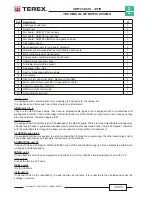
Ref.
Description
N.
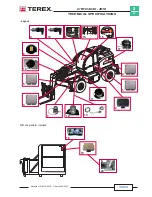
1
Head type central unit
1
2
Limiter unit
1
3
Arm board - ARM C1 front carriage
1
4
Arm board - ARM C2 rear carriage
1
5
Arm board - ARM C3 platform and signals on boom
1
6
Cab Cluster panel
1
7
Servo-assisted reels for outriggers' extension
4
8
Angle/length servo-assisted reel with double transducers
1
9
Main cylinder pressure transducers
2
10
Compensation cylinder pressure transducers
2
11
Undercarriage levelling sensor
1
12
Turntable rotation Rotax sensor
1
13
8-passage rotary joint
1
14
Reel for 6-passage platform signals
1
15
Cab display
1
16
Right control panel (not 3B6) - Radio unit (not 3B6)
1
17
Boom control driver (not 3B6) - Diagnostic connector
1
18
Control console from platform
1
19
Platform weight control unit
1
20
2.5t redundant load cell
1
HEAD unit 1
It is equipped with a microprocessor for managing the movements, the ramps, etc.
It is positioned on a base and has a block programme (interpreter).
ARM units 3, 4, 5
They are the HEAD slave boards; they have no programmable logics but are equipped with micro-switches and
manage the CAN I/O. Their outside aspect is similar to the one of the HEAD, but they have a resin coating as they
are used outdoors. Protection degree IP67.
ROTAX unit 12
It is equipped with an electric joint for the passage of the digital signals. There are three potentiometers changed by
120 degrees in phase to guarantee redudancy (each potentiometer has a dead zone of some 40 degrees, therefore
with the potentiometers changed in phase, we can read the turret position in redundancy).
CLUSTER panel unit 6
It is equipped with two connectors; the small on reads the CAN and the power supply, the other reads relays, right-
hand panel pushbuttons and transfers them all around the machine.
ECOMATRICE unit 16
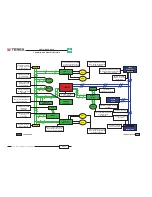
It reads J1939 and CANOpen. ARM and MIDAC read J1939 and HEAD manages it (it can display the information
on engine and transmission).
MIDAC unit 2
It has a flash-memory to save programme and charts in memory. It shall be re-programmed via sw with a PC.
ASA unit 11
It reads the two X and Y axes.
REEL unit 14
It is the CAN bus.
CLIO unit 19
It has two CPUs for the redundancy; it reads the two cell channels. It is connected to the CanBus and saves the
settings in memory.


