background image

3-28 

GTH-1256 AF 

Part No. 57.4400.9219

September 2017

Section 3 • Scheduled Maintenance Procedures

D-6
Perform Axle Maintenance

Note: Axle speci

fi

 cations require that this 

procedure be performed every 1000 hours.

Differential lubricating oil - change
Planetary reduction lubricating oil - change
Dropbox (if any) lubricating oil - change

Required maintenance procedures and additional 
axle information are available in the 

Dana 213 Axle Service Manual 

(Dana part number ASM-0026E).

Dana 213 Axle Service Manual

Genie part number

57.4700.0028

CHECKLIST   D   PROCEDURES

D-7
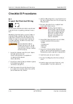
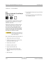
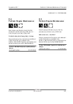
Replace Coolant
Filter Element

Genie speci

fi

 cations require that this procedure 

be performed every 2000 hours or annually, 
whichever comes 

fi

 rst.

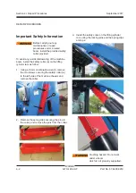
CAUTION

Bodily injury hazard. Beware 
of hot coolant. Contact with 
hot coolant may cause severe 
burns.

1  Remove the cover placed behind the cab.

2  Remove the bottom dome.

3  Pull out and replace the 

fi

 lter cartridge.

Summary of Contents for GTH-1256 AF

Page 1: ...1 Part No 57 4400 9219 Rev C September 2017 Serial Number Range GTH 1256 AF From GTH12AFM 101 Service Manual...

Page 2: ...re specialized skills tools lifting equipment and a suitable workshop In these instances we strongly recommend that maintenance and repair be performed at an authorized dealer service center Technical...

Page 3: ...g C 09 2017 Section 5 6 7 Addition of section 5 renumbering of section 6 and 7 REFERENCE EXAMPLES Perkins Engine_Section 2_Specifications A 5 B 8 C 1 D 5 E 2_Section 3_Maintenance Procedure 4 1 4 2_Se...

Page 4: ...ematic Page Description REFERENCE EXAMPLES Perkins Engine_Section 2_Specifications A 5 B 8 C 1 D 5 E 2_Section 3_Maintenance Procedure 4 1 4 2_Section 4_Repair Procedure Fault Codes_Section 6 Section...

Page 5: ...1256 AF v 3930 01 647 7904 10 000 LBS 49 394 LBS 39 394 LBS GSA BPA GS 07F DA073 12 Mo INTRODUCTION Serial Number legend GTH12AF xxxxx M 5 1 Model 2 Facility code 3 Sequence number 4 Serial number st...

Page 6: ...vi GTH 1256 AF Part No 57 4400 9219 September 2017 This page intentionally left blank...

Page 7: ...identified in the Operator s Manual are also safety hazards when maintenance and repair procedures are performed Do Not Perform Maintenance Unless You are trained and qualified to perform maintenance...

Page 8: ...e clothing if the situation warrants it Be aware of potential crushing hazards such as moving parts free swinging or unsecured components when lifting or placing loads Always wear approved steel toed...

Page 9: ...2 3 Hydraulic Components Specifications 2 4 Function Manifold Specifications 2 5 Air Conditioner Refrigerant Specifications 2 5 Perkins 1104D E44TA Engine 2 6 Dana Integral Gear Box 2 7 Dana Axle 2 7...

Page 10: ...A 8 Perform Axle Maintenance 3 10 A 9 Perform 30 Day Service 3 11 A 10 Perform Axle Maintenance 3 11 A 11 Perform Gear Box Maintenance 3 12 A 12 Perform Axle Maintenance 3 12 A 13 Perform Engine Main...

Page 11: ...s 3 22 Checklist D Procedures D 1 Inspect the Forks 3 24 D 2 Tighten the Boom Chains 3 25 D 3 Replace the Hydraulic Tank Return Filter Element 3 26 D 4 Change Gear Box Oil 3 27 D 5 Perform Engine Main...

Page 12: ...Operator s compartment 2 1 Operator s Compartment 4 17 2 2 Machine Controls 4 19 Fuel and Hydraulic Tanks 3 1 Fuel tank 4 22 3 2 Hydraulic tank 4 23 Engines 4 1 Engine 4 24 4 2 Engine Fault Codes 4 2...

Page 13: ...Heaters 4 46 Webasto Heater 11 1 Webasto Heater 4 50 AC Unit 12 1 AC Unit 4 51 Radiators 13 1 Radiators 4 52 Fuel System 14 1 Fuel System Prime 4 54 Braking Circuit 15 1 Braking circuit 4 55 Section...

Page 14: ...xiv GTH 1256 AF Part No 57 4400 9219 September 2017 Section 7 Schematics Introduction 7 1 Electrical and Hydraulic Symbol Legends 7 2 Electrical Schematic 7 3 Hydraulic Schematic 7 15...

Page 15: ...specifications refer to the Operator s Manual Tires and wheels Tire size 17 5 x 25 Tire ply rating 22 Weight rough terrain tire air filled 449 7 lbs 204 kg Tire pressure models with air filled tires 9...

Page 16: ...4000 lbs 10886 kg Lift capacity maximum 10000 lbs 4536 kg Boom function speeds maximum Boom up 18 seconds Boom down 21 seconds Boom extend 25 seconds Boom retract 33 seconds Fork tilt up 6 seconds For...

Page 17: ...46 Chevron Aviation A Eni Arnica 32 NOTICE The hydraulic oil used in the machine has been chosen based on the temperature range in which the machine will be used The optional oils indicated herein can...

Page 18: ...e pressure maximum measured at test port TP2 2610 psi 180 bar Hydrostatic Transmission Pump Type variable displacement piston pump Displacement 0 to 5 5 cu in 0 to 90 cc Flow rate 2200 rpm 52 gpm 198...

Page 19: ...280 bar Fork tilt relief valve pressure maximum 4350 psi 300 bar Steering Unit Steer relief valve pressure maximum 2610 psi 180 bar Steer anti shock valve pressure setting 3190 psi 220 bar Air Conditi...

Page 20: ...5W 40 API CJ4 low ash oil Extreme operating temperatures may require the use of alternative engine oils For oil requirements refer to the Engine Operation and Maintenance Manual on your machine SPECIF...

Page 21: ...7 Dana Axle Steering Integrated steer cylinder Joints Heavy duty double U joints Steering angle maximum 35 Front Axle Lubrication Front differential 15 5 quarts 14 7 liters Axle planetary end each 1 9...

Page 22: ...10 7 8 14 1 12 1 1 16 12 1 16 1 5 16 12 1 20 1 5 8 12 1 24 1 7 8 12 1 SAE O ring Boss Port tube fitting installed into Aluminum all types SAE Dash size Torque 4 14 ft lbs 19 Nm 6 23 ft lbs 31 2 Nm 8 3...

Page 23: ...ngs 1 Align the tube flare hex nut against the nose of the fitting body body hex fitting and tighten the hex nut to the body hex fitting to hand tight approximately 30 in lbs 3 4 Nm 2 Make a reference...

Page 24: ...THREAD i n l bs N m i n l bs N m i n l bs N m i n l bs N m i n l bs N m 20 80 9 100 11 3 110 12 4 140 15 8 130 14 7 28 90 10 1 120 13 5 120 13 5 160 18 140 15 8 ft l bs N m ft l bs N m ft l bs N m ft...

Page 25: ...ith the machine in the following configuration Machine parked on a firm level surface Boom in the stowed position Key switch in the off position with the key removed Wheels chocked About This Section...

Page 26: ...report to use for each inspection Store completed forms as required Maintenance Schedule There are five types of maintenance inspections that must be performed according to a schedule daily quarterly...

Page 27: ...150 Watertown SD 57201 6150 605 882 4000 Genie UK The Maltings Wharf Road Grantham Lincolnshire NG31 6BH England 44 1476 584333 Copyright 2011 Terex Corporation Genie is a registered trademark of Tere...

Page 28: ...ts A 4 Lubricate the boom A 5 Engine maintenance A 6 Safety devices A 7 Pre Filter Perform after 10 hours A 8 Axle maintenance Perform after 40 hours A 9 30 day service Perform after 100 hours A 10 Ax...

Page 29: ...EAR BOX OIL DIFFERENTIAL OIL PLANETARY REDUCTION OIL DROPBOX OIL 09 4616 0158 SAE GRADE 75W 80 75W 80 75W 80 75W 80 NLGI2 EP or NLGI3 EP NLGI2 EP or NLGI3 EP NLGI2 EP or NLGI3 EP NLGI2 EP or NLGI3 EP...

Page 30: ...could result in unsafe operating conditions 1 Check to make sure that the operator s and safety manuals are present and complete in the storage container in the operator s compartment 2 Examine the p...

Page 31: ...nspection also serves to determine if routine maintenance procedures are required Complete information to perform this procedure is available in the appropriate operator s manual Refer to the Operator...

Page 32: ...ontact surfaces Result Boom operates smoothly and a thin film of lubricant is visible Proceed to step 6 Result Boom does not extend or retract smoothly and no lubricant is visible on wear pad contact...

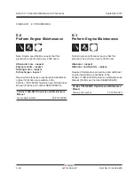
Page 33: ...mission is inhibited Attempt to level the machine It must not be possible because chassis levelling is inhibited CHECKLIST A PROCEDURES A 5 Perform Engine Maintenance Note Engine specifications requir...

Page 34: ...running by turning the fan by hand CHECKLIST A PROCEDURES A 8 Perform Axle Maintenance Note Axle specifications require that this procedure be performed after 10 hours Differential lubricating oil ch...

Page 35: ...ct the Tires Wheels and Lug Nut Torque D 3 Replace the Hydraulic Tank Return Filter Element Check Belt Tension Check The Engine Mounts Check Hose Clamps A 10 Perform Axle Maintenance Note Axle specifi...

Page 36: ...ervice Manual Dana part number GSM 0016 Dana 367 Gear Box Service Manual Genie part number 57 4700 0027 A 12 Perform Axle Maintenance Note Axle specifications require that this procedure be performed...

Page 37: ...Perkins part number SEBU9066 00 Perkins 1104D E44TA Operation and Maintenance Manual Genie part number 57 4700 0029 CHECKLIST A PROCEDURES A 14 Perform Engine Maintenance Note Engine specifications re...

Page 38: ...ielectric grease in the following locations All harness connectors 3 Start the engine and raise the boom so there is enough room to access and remove all the covers attached to the chassis Checklist B...

Page 39: ...every 250 hours or quarterly whichever comes first Maintaining the exhaust system is essential to good engine performance and service life Running the engine with a damaged or leaking exhaust system...

Page 40: ...ocedure be performed every 250 hours or quarterly whichever comes first Maintaining the tires and wheels in good condition including proper wheel fastener torque is essential to safe operation and goo...

Page 41: ...ce life Dirty oil may cause the machine to perform poorly and continued use may cause component damage Extremely dirty conditions may require oil changes to be performed more often Refer to Section 2...

Page 42: ...mobile part of every section All pads can be adjusted by the special shims supplied by GENIE upon demand 1 Extend the boom until the wear pads are accessible 2 Inspect each pad and ensure that the pa...

Page 43: ...ne specifications require that this procedure be performed every 400 hours Aftercooler core clean test Required maintenance procedures and additional engine information are available in the Perkins 11...

Page 44: ...s 1104D E44TA Operation and Maintenance Manual Perkins part number SEBU9066 00 Perkins 1104D E44TA Operation and Maintenance Manual Genie part number 57 4700 0029 C 2 Perform Engine Maintenance Note E...

Page 45: ...ilter change Fuel system primary filter water separator element replace Fuel system secondary filter replace Required maintenance procedures and additional engine information are available in the Perk...

Page 46: ...s in suspension over irregular surfaces and rough terrain Attempting to inch loads which are beyond the rated capacity of the vehicle CHECKLIST C PROCEDURES The load cycles and environmental condition...

Page 47: ...must be lubricated with a quality chain lubricant Note Do not use grease to lubricate chains The chain plates should be brushed with a wire brush prior to lubrication to clear the space between the pl...

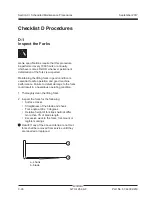
Page 48: ...sential to safe operation and good machine performance Failure to detect damage to the forks could result in a hazardous operating condition 1 Thoroughly clean the lifting forks 2 Inspect the forks fo...

Page 49: ...ems are detected please contact service CHECKLIST D PROCEDURES D 2 Tighten the Boom Chains Genie specifications require that this procedure be performed every 1000 hours or annually whichever comes fi...

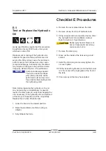
Page 50: ...conditions may require that the filter element be replaced more often CAUTION Bodily injury hazard Beware of hot oil Contact with hot oil may cause severe burns Note Perform this procedure with the e...

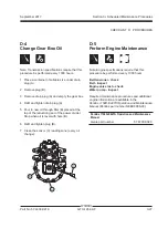
Page 51: ...uction gear of the power divider Stop when oil is level with hole B 6 Refit and tighten plug B 7 Clean the sensor C reading zone every oil change B A C D 5 Perform Engine Maintenance Note Engine speci...

Page 52: ...res and additional axle information are available in the Dana 213 Axle Service Manual Dana part number ASM 0026E Dana 213 Axle Service Manual Genie part number 57 4700 0028 CHECKLIST D PROCEDURES D 7...

Page 53: ...aulic oil the oil may be tested by an oil distributor for specific levels of contamination to verify that changing the oil is necessary If the hydraulic oil is not replaced at the two year inspection...

Page 54: ...E44TA Operation and Maintenance Manual Perkins part number SEBU9066 00 Perkins 1104D E44TA Operation and Maintenance Manual Genie part number 57 4700 0029 E 3 Perform Engine Maintenance Note Engine s...

Page 55: ...1104D E44TA Operation and Maintenance Manual Perkins part number SEBU9066 00 Perkins 1104D E44TA Operation and Maintenance Manual Genie part number 57 4700 0029 E 5 Perform Engine Maintenance Note En...

Page 56: ...3 32 GTH 1256 AF Part No 57 4400 9219 September 2017 Section 3 Scheduled Maintenance Procedures CHECKLIST E PROCEDURES This page intentionally left blank...

Page 57: ...on Most of the procedures in this section should only be performed by a trained service professional in a suitably equipped workshop Select the appropriate repair procedure after troubleshooting the p...

Page 58: ...boom install tha safety collar a on the lifting cylinder ram as follow 1 Using a 13mm combination wrench remove the two screws securing the safety collar a to the left side of the machine chassis and...

Page 59: ...to the top of the lifting fork frame at the front of the boom Support the frame Do not apply any lifting pressure 2 Disconnect the quick fit connectors of the hoses coming from the fork coupling attac...

Page 60: ...rizontal position 3 Fully retract the boom 4 Turn the machine off and remove the key from the key switch 5 At the pivot end of the boom remove pins l and pulleys m 6 Remove the upper screws securing t...

Page 61: ...it to the new chain 14 Using the assistance of a second operator install the chain by pulling the guide rope from the fork end of the boom while the other operator guides the chain from the pivot end...

Page 62: ...Fully retract the boom 4 Turn the machine off and remove the key from the key switch 5 At the pivot end of the boom remove pins l and pulleys m 6 Remove the lower screws securing the lower chains f g...

Page 63: ...vot end of the boom 14 Install the lower screws securing the lower chains f g 15 Remove the guide rope 16 Connect the chain to the anchor plates p by means of the retaining fasteners q 17 Install the...

Page 64: ...oom Do not apply any lifting pressure 6 Attach a second strap from the overhead crane to the lifting cylinder rod side and put some tension on it 7 Using a soft metal drift remove the slave cylinder l...

Page 65: ...metal drift and a hammer remove the rod end pivot pin from the tilt cylinder Keep attention to choose a drift smaller than the pivot pin 3 Remove the bottom end carter of the boom 4 Tag disconnect and...

Page 66: ...nected to the overhead crane sling the first second and third boom out of the fourth one 16 Set the boom assembly on a structure capable of supporting it 17 Let the first and second boom section slide...

Page 67: ...slowly to allow the oil pressure to dissipate gradually Do not allow oil to squirt or spray NOTICE Component damage hazard Hoses can be damaged if they are kinked or pinched 3 Attach a lifting strap...

Page 68: ...re the cylinder retainer 5 Place a container of suitable size under the hydraulic hoses before disconnecting 6 Tag disconnect and plug the hydraulic hoses from the extend cylinder Cap the cylinder fit...

Page 69: ...4 Place a container of suitable size under the hydraulic hoses before disconnecting 5 Tag disconnect and plug the hydraulic hoses from the level cylinder Cap the cylinder fittings WARNING Bodily inju...

Page 70: ...efore replacing a hydraulic hose thoroughly clean the machine including the inside of the boom assembly 2 Tag disconnect and plug both ends of the hydraulic hose to be replaced Cap the fittings WARNIN...

Page 71: ...e cylinder 5 Place a container of suitable size under the hydraulic hoses before disconnecting 6 Tag disconnect and plug the hydraulic hoses from the level cylinder Cap the cylinder fittings WARNING B...

Page 72: ...he proximity switch assembly to the chassis just enough to allow the bracket to move 4 Move the proximity switch assembly until the light of the proximity switch turns on then move the proximity switc...

Page 73: ...ontact with electrically charged circuits could result in death or serious injury Remove all rings watches and other jewelry 3 Remove the protective cover next to the cab inner side of the machine 4 C...

Page 74: ...s to the top the cabin in the special seats 15 Using a sling chain and an overhead crane slowly raise the cabin away from the machine and set it on a supporting device NOTICE Component damage hazard W...

Page 75: ...ove the nut securing the steering wheel to the column and remove the steering wheel 2 2 Machine Controls How to Remove the Steering Column 1 Get behind the front right wheel remove the round protectiv...

Page 76: ...ic oil level in the hydraulic tank will result in excessive hydraulic fluid leaking from the hose Do not disconnect the hose from the port if the joystick is below the hydraulic oil level in the hydra...

Page 77: ...ag disconnect and plug the hydraulic hoses of the brake pedal pump WARNING Bodily injury hazard Spraying hydraulic oil can penetrate and burn skin Loosen hydraulic connections very slowly to allow the...

Page 78: ...t with electrically charged circuits could result in death or serious injury Remove all rings watches and other jewelry 2 Remove the filler cap from the fuel tank 3 Using an approved hand operated pum...

Page 79: ...completely drain the tank CAUTION Bodily injury hazard Beware of hot oil Contact with hot oil may cause severe burns 8 Remove the wire harness from the bulb on the hydraulic filter and from the low o...

Page 80: ...cated on the dashboard in the operator s compartment To learn the specifications of and how to use the fault codes refer to Section 6 Fault Codes 4 1 Engine How to Repair the Perkins 1104D E44TA Engin...

Page 81: ...without these skills and tools could result in death or serious injury and significant component damage Dealer service is required 1 Chock the wheels 2 Remove the fasteners securing the driveshaft to...

Page 82: ...pin to the chassis 10 Use a soft metal drift to remove the pivot pin 11 Remove the fasteners securing the axle to the chassis Remove the axle from the machine WARNING Crushing hazard The axle will fal...

Page 83: ...hing the throttle pedal Result the pressure gauge reads 4060 psi 280 bar The pump is good Pressure is not within specification The pump needs to be adjusted OR the pump or pump coupling is faulty and...

Page 84: ...s 4 Tag disconnect and plug the case drain hose located at the top of the pump Cap the fitting on the pump WARNING Bodily injury hazard Spraying hydraulic oil can penetrate and burn skin Loosen hydrau...

Page 85: ...pump on the transmission pump 2 Install the high pressure hose onto the pump outlet WARNING Bodily injury hazard Spraying hydraulic oil can penetrate and burn skin Loosen hydraulic connections very s...

Page 86: ...gine running move the joystick slowly to verify that the movements are performed correctly 6 Shut off the engine and inspect for oil leaks How to Adjust the Boom and Steering Function Pump Standby Pre...

Page 87: ...ing the valve on the function manifold when the pressure gauge reading is stable Result the pressure gauge reads 4350 psi 300 bar The pump is good Proceed to step 9 Pressure is not within specificatio...

Page 88: ...quipment and a suitable workshop Attempting this procedure without these skills and tools could result in death or serious injury and significant component damage Dealer service is strongly recommende...

Page 89: ...o specification during installation Refer to Section 2 Hydraulic Hose and Fitting Torque Specifications Note Perform this procedure with the engine off and cool to the touch 1 Install the auxiliary ge...

Page 90: ...es How to Prime the Auxiliary Gear Pump 1 Start the engine allow the engine to run at low idle for 15 seconds then shut off the engine 2 Wait 15 seconds then start the engine again 3 Allow the engine...

Page 91: ...uge connected to test port TP3 reads 406 psi 28 bar Pressure is not within specification Adjust the boost pressure valve c located under the pump 5 Increase the engine speed to 1100 rpm 6 Release park...

Page 92: ...Remove the cover that is under engine 4 Locate the battery disconnect switch and disconnect the battery from the machine 5 Remove the retaining fasteners that secure the battery disconnect switch mou...

Page 93: ...e engine housing 3 Remove the cover that is under engine 4 Attach a lifting strap and lift the transmission pump using a overhead crane 5 Install the hydrostatic transmission pump on the engine 6 Remo...

Page 94: ...he engine Run at low idle for 5 seconds Shut the engine off and wait for 15 seconds 3 Start the engine Run at low idle for 10 seconds Shut the engine off and wait for 15 seconds 4 Note Repeat step 4 u...

Page 95: ...ecifications Note Perform this procedure with the engine off and cool to the touch 1 Close the hydraulic tank ball valves 2 Remove the central cover of the machine 3 Tag disconnect and plug the hoses...

Page 96: ...l tank 2 Connect a 0 to 5000 psi 0 to 350 bar pressure gauge to port TP1 main valve hydraulic circuit test port 3 Start the engine 4 Increase the engine speed to maximum rpm 5 Moving the joystick retr...

Page 97: ...c proportional control A1 B1 b Boom in out Hydraulic proportional control A2 B2 c Chassis sway Hydraulic proportional control A3 B3 d Fork tilt down up Hydraulic proportional control A4 B4 e Attachmen...

Page 98: ...njury Remove all rings watches and other jewelry Note If the machine has been in operation allow the coil to cool at least 3 hours before performing this test 1 Tag and disconnect the wiring from the...

Page 99: ...should read 9V DC or more when measured across the terminals 3 Set a multimeter to read DC current Note The multimeter when set to read DC current should be capable of reading up to 800 mA 4 Connect...

Page 100: ...e pivot pin 5 Place a container of suitable size under the hydraulic hoses before disconnecting 6 Tag disconnect and plug the hydraulic hoses from the level cylinder Cap the cylinder fittings WARNING...

Page 101: ...the Fork Positioning Cylinders 1 Start the engine 2 Shift the forks to end of stroke to the left and to the right Result The forks travel synchronously and reach the end of stroke at the same time St...

Page 102: ...ting element a 1 Remove the cover placed behind the cab 2 Disconnect the power wire of the heating element from the oil tank side 3 Close the oil intake valves 4 Remove the cover on the top of the oil...

Page 103: ...kit apply maximum pressure as you affix the pad Carefully avoid wrinkles or creases smooth the entire pad to the surface 9 Attach the first length of AC cord with a cord tie supplied in kit This preve...

Page 104: ...3 Disconnect the power wire from the heating element 4 Loosen the retaining fasteners and remove the heating element POWER PLANT HEATERS Replacing the battery pad d 1 Open the engine compartment 2 Di...

Page 105: ...Disconnect the power wire of the heated blanket from the relevant branch box 4 Cut and remove the ties securing the blanket to the battery e Replacing the battery charger f 1 Open the engine compartm...

Page 106: ...basto heater to the fittings at the rear of the cabin 3 Remove the retaining collars and disconnect the drain and filter hoses 4 Disconnect the fuel feed hose 5 Remove the retaining bolts to free and...

Page 107: ...ke a filling pump similar to the one in the next image 4 Using an appropriate adapter connect the pump return hose to the appropriate fitting that is on the hose connected to the S port of the compres...

Page 108: ...move the two knobs securing the cover on the rear lower side of the engine housing and remove the cover Radiators 3 Clean the water oil radiator with compressed air to eliminate all the sand from the...

Page 109: ...en cover a 3 Remove the two knobs securing the grid b to the inner side of the chassis and remove the grid 4 Clean the oil radiator with compressed air to eliminate all the sand from the fins 5 Elimin...

Page 110: ...ngth of clear hose attached to be used NOTICE The electric priming pump will only operate with the keyswitch in the OFF position 5 With tool installed to valve b press button c and keep the button dep...

Page 111: ...the rear axle has 2 bleed screws for the service brake 1 Reach the front axle Steer the machine wheels for more comfortable access to the service area if necessary Braking circuit 2 Remove the protect...

Page 112: ...4 56 GTH 1256 AF Part No 57 4400 9219 September 2017 Section 4 Repair Procedures This page intentionally left blank...

Page 113: ...ollowing check to the engine Carefully check all drive belts paying particular attention to the point where the straight run of the belt starts to bend around the pulley Check the vee groove in the pu...

Page 114: ...5 2 GTH 1256 AF Part No 57 4400 9219 September 2017 Section 5 Long Term Storage Recommendation This page intentionally left blank...

Page 115: ...ructions in the appropriate operator s manual on your machine Be sure that all necessary tools and test equipment are available and ready for use Be aware of the following hazards and follow generally...

Page 116: ...ve fault codes page press the diagnostic button d and hold it pressed for at least 5 seconds Active Codes vs Stored Codes Active fault codes indicating an engine condition or conditions which have not...

Page 117: ...Pulse Width or Period 100 03 Engine Oil Pressure Sensor Voltage Above Normal 100 04 Engine Oil Pressure Sensor Voltage Below Normal 100 10 Engine Oil Pressure Sensor Abnormal Rate of Change 110 03 Eng...

Page 118: ...Sensor Voltage Above Normal 157 04 Fuel Rail Pressure Sensor Voltage Below Normal 158 02 Ignition Key Swtich Loss of Signal 676 05 Glow Plug Start Aid Relay Current Above Normal 676 06 Glow Plug Start...

Page 119: ...nd test equipment are available and ready for use About This Section There are two groups of schematics in this section An illustration legend precedes each group of drawings Electrical Schematics WAR...

Page 120: ...Flow regulator Relief valve 3 position 4 way proportional directional valve 2 position 3 way directional valve 3 position 4 way solenoid valve 2 position 4 way solenoid valve 2 position 2 way solenoi...

Page 121: ...September 2017 Part No 57 4400 9219 GTH 1256 AF 7 3 Section 7 Schematics ELECTRICAL SCHEMATIC Sheet 1 of 11 From SN GTH12AFM 101...

Page 122: ...7 4 GTH 1256 AF Part No 57 4400 9219 September 2017 Section 7 Schematics Sheet 2 of 11 From SN GTH12AFM 101 ELECTRICAL SCHEMATIC...

Page 123: ...September 2017 Part No 57 4400 9219 GTH 1256 AF 7 5 Section 7 Schematics Sheet 3 of 11 From SN GTH12AFM 101 ELECTRICAL SCHEMATIC...

Page 124: ...7 6 GTH 1256 AF Part No 57 4400 9219 September 2017 Section 7 Schematics Sheet 4 of 11 From SN GTH12AFM 101 ELECTRICAL SCHEMATIC...

Page 125: ...September 2017 Part No 57 4400 9219 GTH 1256 AF 7 7 Section 7 Schematics Sheet 5 of 11 From SN GTH12AFM 101 ELECTRICAL SCHEMATIC...

Page 126: ...7 8 GTH 1256 AF Part No 57 4400 9219 September 2017 Section 7 Schematics Sheet 6 of 11 From SN GTH12AFM 101 ELECTRICAL SCHEMATIC...

Page 127: ...September 2017 Part No 57 4400 9219 GTH 1256 AF 7 9 Section 7 Schematics Sheet 7 of 11 From SN GTH12AFM 101 ELECTRICAL SCHEMATIC...

Page 128: ...7 10 GTH 1256 AF Part No 57 4400 9219 September 2017 Section 7 Schematics Sheet 8 of 11 From SN GTH12AFM 101 ELECTRICAL SCHEMATIC...

Page 129: ...September 2017 Part No 57 4400 9219 GTH 1256 AF 7 11 Section 7 Schematics Sheet 9 of 11 From SN GTH12AFM 101 ELECTRICAL SCHEMATIC...

Page 130: ...7 12 GTH 1256 AF Part No 57 4400 9219 September 2017 Section 7 Schematics Sheet 10 of 11 From SN GTH12AFM 101 ELECTRICAL SCHEMATIC...

Page 131: ...September 2017 Part No 57 4400 9219 GTH 1256 AF 7 13 Section 7 Schematics Sheet 11 of 11 From SN GTH12AFM 101 ELECTRICAL SCHEMATIC...

Page 132: ...7 14 GTH 1256 AF Part No 57 4400 9219 September 2017 Section 7 Schematics This page intentionally left blank...

Page 133: ...September 2017 Section 7 Schematics 7 15 7 16 Hydraulical Schematic Perkins Engine...

Page 134: ...s 6 450 psi Hydrostatic transmission high pressure test port X7 X8 TP3 TP4 Tp1 TP5 Hydrostatic transmission boost pressure test port Hydrostatic transmission pump charge displacement c rev 1 20 i Rear...

Reviews: