Service and Repair Manual
November 2020
Control System Fault Codes
80
Z
®
-45 XC
™
• Z
®
-45 HF
Part No. 1268197GT
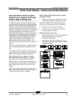
How t o R etrieve Contr ol Syst em F ault Codes
Control System
How to Retrieve Control System
Fault Codes
At least one fault code is present when the alarm
at the platform controls produces two short beeps
every 30 seconds for 10 minutes.
Perform this procedure with the engine off, the key
switch turned to platform controls and the red
Emergency Stop button pulled out to the on
position at both the ground and platform controls.
1
Open the platform control box lid.
Electrocution/burn hazard.
Contact with electrically charged
circuits could result in death or
serious injury. Remove all rings,
watches and other jewelry.
2
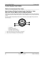
Locate the red and yellow fault LEDs on the
ALC-500 circuit board inside the platform
control box. Do not touch the circuit board.
Component damage hazard.
Electrostatic discharge (ESD)
can damage printed circuit board
components. Maintain firm
contact with a metal part of the
machine that is grounded at all
times when handling printed
circuit boards OR use a
grounded wrist strap.
3
Determine the error source:
The red LED
indicates the error source and will flash two
separate codes. The first code will indicate
the first digit of the two digit code, flashing
once per second. It will then pause for
1.5 seconds and flash the second digit once
per 0.5 second.
Note: When the red LED is flashing the code, the
yellow LED will be on solid.
4
Determine the error type:
The yellow LED
indicates the error type and will flash two
separate codes. The first code will indicate
the first digit of the two digit code, flashing
once per second. It will then pause for
1.5 seconds and flash the second digit once
per 0.5 second.
Note: When the yellow LED is flashing the code,
the red LED will be on solid.
5
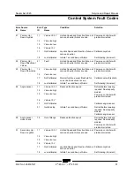
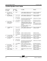
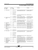
Use the fault code table on the following
pages to aid in troubleshooting the machine
by pinpointing the area or component
affected.
Summary of Contents for Genie Z-45 XC
Page 69: ...November 2020 Service and Repair Manual Manifolds Part No 1268197GT Z 45 XC Z 45 HF 57 ...
Page 71: ...November 2020 Service and Repair Manual Manifolds Part No 1268197GT Z 45 XC Z 45 HF 59 ...
Page 73: ...November 2020 Service and Repair Manual Manifolds Part No 1268197GT Z 45 XC Z 45 HF 61 ...
Page 75: ...November 2020 Service and Repair Manual Manifolds Part No 1268197GT Z 45 XC Z 45 HF 63 ...
Page 83: ...November 2020 Service and Repair Manual Manifolds Part No 1268197GT Z 45 XC Z 45 HF 71 ...
Page 143: ...November 2020 Service and Repair Manual 131 Electrical Schematic Ford MSG425 ...
Page 147: ...November 2020 Service and Repair Manual 135 Electrical Schematic Deutz D 2 9 L4 ...
Page 150: ...Service and Repair Manual November 2020 138 Engine Wire Harness Deutz D 2 9 L4 ...
Page 151: ...November 2020 Service and Repair Manual 139 Electrical Schematic Deutz TD 2 2 L3 ...
Page 154: ...Service and Repair Manual November 2020 142 Engine Wire Harness Deutz TD 2 2 L3 Page 1 ...
Page 156: ...Service and Repair Manual November 2020 144 Engine Wire Harness Deutz TD 2 2 L3 Page 2 ...
Page 157: ...November 2020 Service and Repair Manual 145 Electrical Schematic Perkins 404F E22T ...
Page 160: ...Service and Repair Manual November 2020 148 Engine Wire Harness Perkins 404F E22T ...
Page 161: ...November 2020 Service and Repair Manual 149 Electrical Schematic Function Controls ANSI CSA ...
Page 164: ...Service and Repair Manual November 2020 152 Electrical Schematic Function Controls CE ...
Page 165: ...November 2020 Service and Repair Manual 153 Electrical Schematic Platform Overload ...
Page 168: ...Service and Repair Manual November 2020 156 Electrical Schematic Options Wiring Diagram ...
Page 181: ...November 2020 Service and Repair Manual 169 Ground Control Box Switch Panel Wiring Diagram CE ...
Page 185: ...November 2020 Service and Repair Manual 173 Platform Control Box Switch Panel Wiring Diagram ...
Page 192: ...Service and Repair Manual November 2020 180 Platform Control Box Relay Wiring Diagram CE ...
Page 193: ...November 2020 Service and Repair Manual 181 Hydraulic Schematic CE to Z4525XCM 1500 ...
Page 197: ......

