November 2020
Service and Repair Manual
Fault Codes
Part No. 1268197GT
Z
®
-45 XC
™
• Z
®
-45 HF
79
Section 4
Faul t Codes
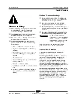
Observe and Obey:
Troubleshooting and repair procedures shall
be completed by a person trained and
qualified on the repair of this machine
Immediately tag and remove from service a
damaged or malfunctioning machine.
Repair any machine damage or malfunction
before operating the machine.
Unless otherwise specified, perform each
procedure with the machine in the following
configuration:
Machine parked on a firm, level surface
Key switch in the off position with the key
removed
The red Emergency Stop button in the off
position at both the ground and platform
controls
Wheels chocked
All external AC power supply disconnected
from the machine
Boom in the stowed position
Turntable secured with the turntable rotation
lock
Welder disconnected from the machine (if
equipped with the weld cable to platform
option)
Before Troubleshooting:
Read, understand and obey the safety rules
and operating instructions in the appropriate
operator's manual on your machine.
Be sure that all necessary tools and test
equipment are available and ready for use.
Read each appropriate fault code thoroughly.
Attempting short cuts may produce hazardous
conditions.
Be aware of the following hazards and follow
generally accepted safe workshop practices.
Electrocution/burn hazard.
Contact with electrically charged
circuits could result in death or
serious injury. Remove all rings,
watches and other jewelry.
Note: Two persons will be required to safely
perform some troubleshooting procedures.
About This Section
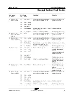
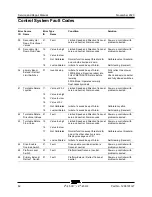
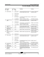
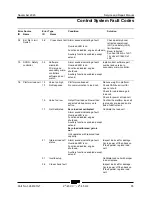
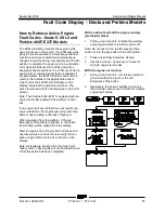
There are two types of system faults in this
section.
Control System Faults:
Faults are indicated by
the ALC500 operating system with two short
beeps every 30 seconds when an abnormal
condition or component failure occurs with the
machine operating system. This could include
machine functions, limit switches, angle sensors
and hydraulic valves. Control system faults can be
retrieved inside the platform control box.
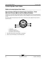
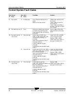
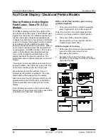
Platform Overload System Fault Codes:
Faults
are indicated on the hour meter display, a red LED
and with one short beep every second when an
abnormal condition or component failure occurs
with the platform overload system. Platform
overload system fault codes can be retrieved on
the hour meter display located at the ground
controls.
Summary of Contents for Genie Z-45 XC
Page 69: ...November 2020 Service and Repair Manual Manifolds Part No 1268197GT Z 45 XC Z 45 HF 57 ...
Page 71: ...November 2020 Service and Repair Manual Manifolds Part No 1268197GT Z 45 XC Z 45 HF 59 ...
Page 73: ...November 2020 Service and Repair Manual Manifolds Part No 1268197GT Z 45 XC Z 45 HF 61 ...
Page 75: ...November 2020 Service and Repair Manual Manifolds Part No 1268197GT Z 45 XC Z 45 HF 63 ...
Page 83: ...November 2020 Service and Repair Manual Manifolds Part No 1268197GT Z 45 XC Z 45 HF 71 ...
Page 143: ...November 2020 Service and Repair Manual 131 Electrical Schematic Ford MSG425 ...
Page 147: ...November 2020 Service and Repair Manual 135 Electrical Schematic Deutz D 2 9 L4 ...
Page 150: ...Service and Repair Manual November 2020 138 Engine Wire Harness Deutz D 2 9 L4 ...
Page 151: ...November 2020 Service and Repair Manual 139 Electrical Schematic Deutz TD 2 2 L3 ...
Page 154: ...Service and Repair Manual November 2020 142 Engine Wire Harness Deutz TD 2 2 L3 Page 1 ...
Page 156: ...Service and Repair Manual November 2020 144 Engine Wire Harness Deutz TD 2 2 L3 Page 2 ...
Page 157: ...November 2020 Service and Repair Manual 145 Electrical Schematic Perkins 404F E22T ...
Page 160: ...Service and Repair Manual November 2020 148 Engine Wire Harness Perkins 404F E22T ...
Page 161: ...November 2020 Service and Repair Manual 149 Electrical Schematic Function Controls ANSI CSA ...
Page 164: ...Service and Repair Manual November 2020 152 Electrical Schematic Function Controls CE ...
Page 165: ...November 2020 Service and Repair Manual 153 Electrical Schematic Platform Overload ...
Page 168: ...Service and Repair Manual November 2020 156 Electrical Schematic Options Wiring Diagram ...
Page 181: ...November 2020 Service and Repair Manual 169 Ground Control Box Switch Panel Wiring Diagram CE ...
Page 185: ...November 2020 Service and Repair Manual 173 Platform Control Box Switch Panel Wiring Diagram ...
Page 192: ...Service and Repair Manual November 2020 180 Platform Control Box Relay Wiring Diagram CE ...
Page 193: ...November 2020 Service and Repair Manual 181 Hydraulic Schematic CE to Z4525XCM 1500 ...
Page 197: ......


