Service and Repair Manual
November 2020
Manifolds
64
Z
®
-45 XC
™
• Z
®
-45 HF
Part No. 1268197GT
8-2 Valve Adjustments - Function
Manifold
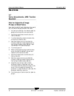
How t o Adj ust t he System Reli ef Val ve
How to Adjust the System Relief
Valve
Note: Perform this procedure with the boom in the
stowed position.
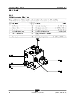
Note: Refer to Function Manifold Component list to
locate the system relief valve.
1
Connect a 0 to 5000 psi / 0 to 350 bar
pressure gauge to the test1 port on the
function manifold.
2
Start the engine from the ground controls.
3
Hold the function enable switch to the high
rpm position and activate and hold the
primary boom retract switch with the boom
fully retracted.
4
Observe the pressure reading on the pressure
gauge. Refer to Specifications,
Hydraulic
Specifications
.
5
Turn the engine off. Use a wrench to hold the
relief valve and remove the cap.
6
Adjust the internal hex socket. Turn it
clockwise to increase the pressure or
counterclockwise to decrease the pressure.
Install the relief valve cap.
Tip-over hazard. Do not adjust
the relief valve higher than
specified.
7
Repeat steps 2 through 5 and recheck relief
valve pressure.
8
Remove the pressure gauge.
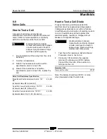
How t o Adj ust t he Sec ondary Boom D own Relief Val ve
How to Adjust the Secondary
Boom Down Relief Valve
Note: Perform this procedure with the boom in the
stowed position.
Note: Refer to Function Manifold Component list to
locate the secondary boom down relief valve.
1
Connect a 0 to 5000 psi / 0 to 350 bar
pressure gauge to the test1 port on the
function manifold.
2
Start the engine from the ground controls.
3
Hold the function enable switch to the high
rpm position and activate and hold the
secondary boom down switch with the
secondary boom fully lowered.
4
Observe the pressure reading on the pressure
gauge. Refer to Specifications,
Hydraulic
Specifications
.
5
Turn the engine off. Use a wrench to hold the
relief valve and remove the cap.
6
Adjust the internal hex socket. Turn it
clockwise to increase the pressure or
counterclockwise to decrease the pressure.
Install the relief valve cap.
Tip-over hazard. Do not adjust
the relief valve higher than
specified.
7
Repeat steps 2 through 5 and recheck relief
valve pressure.
8
Remove the pressure gauge.
Summary of Contents for Genie Z-45 XC
Page 69: ...November 2020 Service and Repair Manual Manifolds Part No 1268197GT Z 45 XC Z 45 HF 57 ...
Page 71: ...November 2020 Service and Repair Manual Manifolds Part No 1268197GT Z 45 XC Z 45 HF 59 ...
Page 73: ...November 2020 Service and Repair Manual Manifolds Part No 1268197GT Z 45 XC Z 45 HF 61 ...
Page 75: ...November 2020 Service and Repair Manual Manifolds Part No 1268197GT Z 45 XC Z 45 HF 63 ...
Page 83: ...November 2020 Service and Repair Manual Manifolds Part No 1268197GT Z 45 XC Z 45 HF 71 ...
Page 143: ...November 2020 Service and Repair Manual 131 Electrical Schematic Ford MSG425 ...
Page 147: ...November 2020 Service and Repair Manual 135 Electrical Schematic Deutz D 2 9 L4 ...
Page 150: ...Service and Repair Manual November 2020 138 Engine Wire Harness Deutz D 2 9 L4 ...
Page 151: ...November 2020 Service and Repair Manual 139 Electrical Schematic Deutz TD 2 2 L3 ...
Page 154: ...Service and Repair Manual November 2020 142 Engine Wire Harness Deutz TD 2 2 L3 Page 1 ...
Page 156: ...Service and Repair Manual November 2020 144 Engine Wire Harness Deutz TD 2 2 L3 Page 2 ...
Page 157: ...November 2020 Service and Repair Manual 145 Electrical Schematic Perkins 404F E22T ...
Page 160: ...Service and Repair Manual November 2020 148 Engine Wire Harness Perkins 404F E22T ...
Page 161: ...November 2020 Service and Repair Manual 149 Electrical Schematic Function Controls ANSI CSA ...
Page 164: ...Service and Repair Manual November 2020 152 Electrical Schematic Function Controls CE ...
Page 165: ...November 2020 Service and Repair Manual 153 Electrical Schematic Platform Overload ...
Page 168: ...Service and Repair Manual November 2020 156 Electrical Schematic Options Wiring Diagram ...
Page 181: ...November 2020 Service and Repair Manual 169 Ground Control Box Switch Panel Wiring Diagram CE ...
Page 185: ...November 2020 Service and Repair Manual 173 Platform Control Box Switch Panel Wiring Diagram ...
Page 192: ...Service and Repair Manual November 2020 180 Platform Control Box Relay Wiring Diagram CE ...
Page 193: ...November 2020 Service and Repair Manual 181 Hydraulic Schematic CE to Z4525XCM 1500 ...
Page 197: ......


